Industry News, Trends and Technology, and Standards Updates

EDA Applications and Benefits for Smart Manufacturing Episode 6: Trace Data Analysis

Posted by Alan Weber: Vice President, New Product Innovations on Oct 25, 2018 11:20:00 AM

In this final article of the “EDA Application and Benefits” series we discuss an application that is one of the most basic and intuitive, but also provides the foundation for the many of the emerging capabilities in the machine learning and artificial intelligence (AI) domain—trace data analysis. Moreover, of all the applications we’ve introduced over the past 6 months, trace data analysis is the one that most directly leverages the capabilities of the SEMI Equipment Data Acquisition (EDA) standards

Problem Statement

When we ask fab process engineers and their supporting automation teams why they are now requiring the latest SEMI EDA/Interface A standards on their new equipment, the answer we hear most often is “To better understand equipment and process behavior.” And when asked why this cannot be achieved using the SECS/GEM interfaces, the answers are equally consistent: “The detailed information we need is either unavailable or cannot be collected at the frequencies we need to accurately see and characterize the behaviors we are interested in. And even if this were possible, we don’t have the operational freedom to change our data collection systems as quickly as our needs change, so we must have a more flexible approach.” 

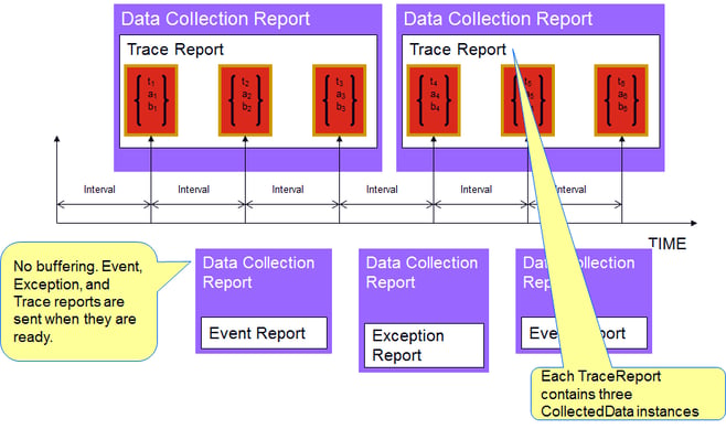
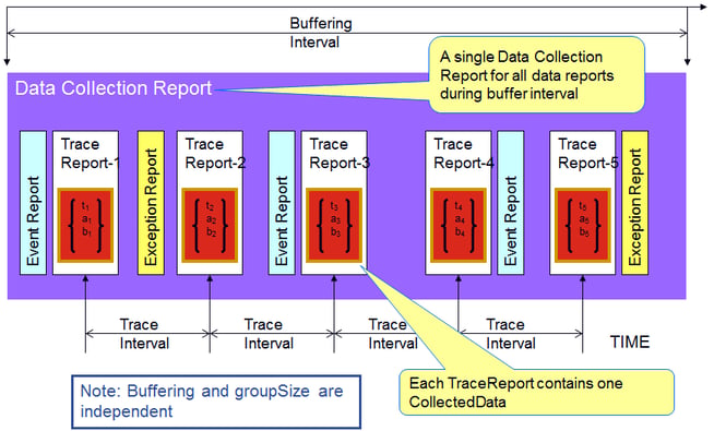
What these engineers are looking for as a starting point is a way to easily specify a list of potentially related equipment parameters and collect their values at a rate that is fast enough to see how they are changing in relationship to one another. Human beings are wonderful at pattern recognition, and simply being able to juxtapose a set of signals on a “strip chart” display (see first figure below) can yield important insights into the underlying process. Of course, this capability is most useful when the engineer can precisely specify the timeframe of interest for this visual analysis. This is sometimes called data “framing” and can be accomplished by using equipment events to bracket the period of interest (see second figure below).

eda_apps_benefits6.1-1-1

EDA_apps_Benefits6.2-1

While humans may be good at pattern recognition, they quickly get overwhelmed when the number of parameters to view grows and/or the timespan to consider expands… which is where trace data analysis software enters the picture.

Solution Components

In addition to very flexible time-series data visualization tools, trace data analysis software packages must be able to “slice and dice” subsets of large data sets to compare every imaginable combination of equipment instance, process chamber, product, layer, recipe, fixture, consumable batch, shift, operator, … (you get the picture) to look for correlations between important factory metrics and the behavior of the equipment involved. Moreover, they must be able to identify and flag “abnormal” (which must be flexibly defined) situations for further analysis, since these may hold clues about incipient failures that traditional multivariate FDC (fault detection and classification) applications may not catch.

In fact, there is an emerging school of thought for fault detection that states “most of the time, the equipment is making good wafers, so unless there’s something very different about the tool behavior between the most recent lots and the current lot (as determined through trace data analysis), it’s very likely that the current lot is good as well.” This simplified approach has also been called “model-less FDC” because it mostly compares trace data signals rather than passing tool parameters into highly context-specific multivariate statistics-based models.

Of course, any trace data analysis application is only as good as the data that feeds it… which is where the EDA standards and the related equipment purchase specifications come into the picture.

EDA (Equipment Data Acquisition) Standards Leverage

Previous postings such as Episode 4 on Fault Detection and Classification and Precision Data Framing during Process Execution – Tricks of the Trade have highlighted the capabilities of the Freeze II EDA standards related to Data Collection Plans (DCPs) and the Trace Requests, Event Requests, and Exception Requests that comprise them. We have also highlighted the need for broad stakeholder involvement when creating the EDA section of an equipment purchase specification and described the process we’ve crafted to accomplish this.

However, to fully support a world-class trace data analysis application, it’s important to understand what to ask of the equipment suppliers. To this end, we’ve excerpted some key sample requirements from a typical purchase specification below.

  • Equipment Model Content (SEMI E120, E125, E164)

    • The hierarchical depth of the metadata model should include at least the “field replaceable unit” (FRU) level, and one of two levels below this for complex sub-systems.
    • The metadata model must contain command and status information for all equipment components that affect material movement. This includes not only material transfer elements such as robot arms, but also devices that may inhibit/enable material movement, such as gate valves, interlocks, etc.
    • The metadata model must include control parameters for all significant operating mechanisms and subsystems in the equipment. The control parameters may include but are not limited to: process variable setpoints and status values; control variable status values; PID tuning parameters, control limits, and calibration constants.
    • The metadata model must include whatever additional usage counters, timers, and other parameters that may be useful in time-based, usage-based, and condition-based maintenance scheduling algorithms.
    • The metadata model must contain parameters the describe consumption rates and levels for key process resources such as electricity, process gases, and other consumables. These are used in some of the FDC models to detect potentially abnormal process conditions.
    • Suppliers must provide a written description of the update rates, recommended sampling intervals, normal operating ranges and behaviors, and high/low/rate-of-change limits for all key process parameters.
    • Etc.

  • Data Collection Capability (SEMI E134)

    • Equipment must include built-in DCPs to support common equipment performance monitoring, diagnostic, and maintenance processes that are well known to the supplier. Documentation for these DCPs must define their purpose, activation conditions, interface bandwidth consumed, and the types of analysis the collected data enables.
    • Equipment parameters provided through the EDA interface must exhibit a number of data quality characteristics, including, but not limited to: an internal sampling/update rate sufficient to represent the underlying signal accurately; timing of trace reports that is consistent with the sampling interval within +/- 1.0%; values in adjacent trace reports must contain then-current values at the specified sampling interval; and rejection of obvious outliers.

  • Performance Requirements

    • Performance requirements will be expressed as combinations of sampling interval, # parameters per DCP, # of simultaneously active DCPs, group size, buffering interval, response time for ad hoc “one-shot” DCPs, maximum latency of event generation after the related equipment condition occurred, consistency of timestamps in trace reports with the specified sampling interval, and perhaps others.
    • Example: The EDA interface must be capable of reporting at least 5000 parameters at a sampling interval of 0.1 seconds (10Hz) with a Group Size of 1, for a total data collection capacity (bandwidth) of 50,000 parameters per second. It must also support simultaneous data collection from at least 5 clients while still achieving a total bandwidth of 50,000 parameters per second; Group Sizes greater than 1 may be used to achieve this level of performance.
    • Some equipment types may have more stringent performance requirements than others, depending on the criticality of timely and high-density data for the consuming applications.

apc2017_5KPIs Affected

Trace data analysis will undoubtedly take its place among the other “mission-critical” applications in today’s fabs because of the increasing process complexity and the need to maintain the traditional “time to yield” production ramp. This is especially true for the industry pioneers now using the latest EUV scanners, as there will be much to learn about this new technology in the coming years.

Let Us Hear from You!

EDA_apps_benefits_6

If you want to understand how the latest EDA standards and trace data analysis can support your future manufacturing objectives, or how to make this a reality in your Smart Manufacturing roadmap, please schedule a meeting!

Schedule a Meeting

Topics: EDA/Interface A, Smart Manufacturing/Industry 4.0, EDA in Smart Manufacturing Series

台灣印刷電路板協會, TPCA (Taiwan Printed Circuit Board) Show is coming up: Will we see you there?

Posted by Michael Lee; Country Manager Taiwan on Oct 17, 2018 11:46:00 AM

Michael Lee of Cimetrix Taiwan talks about the upcoming TPCA show. Read now in Chinese or below in English.

TPCA(台灣印刷電路板協會)2018展會即將到來,我們很高興能連續第二年參展!該展將於10月24日至26日在台北南港展覽中心舉行。 TPCA展會旨在實現智能製造,因為印刷電路板行業與上游和下游的價值鏈相連。預計今年展會將有400多家參展商。

TPCA

TPCA展會匯集了PCB製造商,SMT設備製造商和測試人員,綠色環境設備和材料製造行業,熱模塊相關設備,包裝和表面處理。

Cimetrix很高興參與此次展會,我們將討論我們用於智能製造的創新軟件產品如何幫助設備製造商和工廠。

歡迎光臨我們的I-226展台,或隨時在我們的活動網頁上預約會議!


The TPCA (Taiwan Printed Circuit Board Association) 2018 show is almost here and Cimetrix is excited to be exhibiting for the second year in a row! The show will be held at the Taipei Nangang Exhibition Center from October 24-26. One key theme of this year's TPCA show is the realization of Smart Manufacturing as the printed circuit board industry connects members of its value chain both upstream and downstream. More than 400 exhibitors are expected to be at the show this year.TPCA

The TPCA show brings together PCB manufacturers, SMT manufacturing and test equipment suppliers, Green environment equipment and material manufacturing industries, and suppliers of thermal-modules packaging and surface finishing equipment. 

Cimetrix is excited to be a part of this show, where we discuss how our innovative software products for Smart Manufacturing can help both the equipment suppliers and the PCB manufacturing companies

Come visit us at booth I-226 and/or request a meeting any time on our Events page!

Meet with Us

Topics: Doing Business with Cimetrix, Events, Global Services, Smart Manufacturing/Industry 4.0

SECS/GEM Series: GEM Control State

Posted by Mark Bennett; Client Support Engineer on Oct 11, 2018 10:59:00 AM

What is GEM Control State?

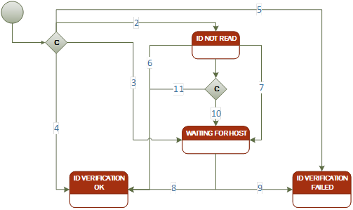
The GEM Control State is one of the fundamental E30 GEM requirements. It defines the level of cooperation between the host and equipment and specifies how the operator may interact at the different levels of host control.

In a semiconductor factory, the host or operator may be in control of equipment processing. Having both sides in control of the equipment at the same time poses problems. When one side is in control of the equipment, the other side should be limited in the operations it can perform. For example, if an operator pauses processing, the host should not be allowed to send commands to resume processing or to start a new job. The GEM Control State is provided to prevent these types of issues from occurring.

SEMI E30 GEM Control State ModelFigure 1: SEMI E30 GEM Control State Model

How does the Control State work?

The Control State provides three basic levels of control. Each level describes which operations may be performed by the host and equipment sides.

Remote

  • The host may control the equipment to the fullest extent possible.
  • The equipment may impose limits on the local operator’s ability to control the equipment, but this is not a requirement of the standard. The host must be capable of handling unexpected commands invoked by the operator at the equipment.
  • GEM Remote Commands are used by the host to invoke commands on the equipment.

Local

  • The operator may control the equipment to the full extent possible.
  • The host has full access to information. The host can collect data using other GEM features such as collection events, traces, and status data collection.
  • Limits are placed on how the host can affect equipment operations:
    • Remote commands that initiate processing (e.g. START) or cause physical movement are prohibited. During processing, remote commands that affect processing (STOP, ABORT, PAUSE, RESUME) are also prohibited.
    • Other remote commands that do not initiate processing, cause physical movement, or affect processing may be allowed.
    • During processing, the host is prohibited from modifying any equipment constants that affect that process.
    • Equipment constants that do not affect the currently running process may be changed.
    • All equipment constants are changeable when not processing.

Offline

  • The operator has complete control of the equipment.
  • The host has no control over equipment operations and very limited information gathering capabilities.
  • The only messages that the equipment will accept from the host are:
    • Messages used to establish GEM communication (S1F13/F14).
    • Requests to activate Online Control State (S1F17), but only if the currently active state is Host Offline (transition #11 on the Control State Model).
    • S1F2 “Are You There Response” while the attempting to go Online.
  • The only primary messages that the equipment may send to the host are:
    • Messages used to establish communications (S1F13).
    • S9Fx messages, but only in response to the messages to which the equipment will normally respond to while Offline (i.e., S1F13 and S1F17).
    • S1F1 “Are You There Request” is sent to the host when the “Attempt ON-LINE” sub-state is entered. This message is used to get permission from the host to transition into an Online state (transition #5).
  • No messages are spooled while Offline.

The Control State Model was designed in a way to give the equipment operator more control over the state machine than the host.  This protects the operator from unexpected state changes initiated from the host.

  • The equipment operator can choose which Online sub-state is active through the operator interface. The host side cannot choose which Online sub-state is active.
  • The equipment side can put the Control State Model into an Equipment Offline state (transition #6). When in this state, the host cannot request to go Online.
  • The host side can put the Control State into a Host Offline state (transition #10), but the equipment side could reject this request. When in the Host Offline state, the equipment side can always attempt to go Online by first transitioning into the Equipment Offline state (transition #12) followed by an attempt to go Online (transition #3).

Operator Interface Requirements

The equipment must provide a way of displaying the current Control State to let the operator know who is in control of the equipment.

The equipment must provide a momentary switch to initiate the transition to the Equipment Offline state, and another switch to attempt to go Online from the Equipment Offline state. This may be a hardware switch on the front panel, but is often implemented in software using button controls.

The equipment must provide a discrete two-position switch which the operator may use to indicate the desired Online sub-state (Local or Remote). This may be a hardware switch on the front panel, but is often implemented in software using button controls. If implemented in software, the setting must be saved in non-volatile storage.

Conditional State Transitions

In the Control State Model, transitions #1, #2, #4, and #7 are conditional state transitions. The equipment application must provide a way of configuring which state to transition into. Equipment constants may be used for these configuration settings.

Conditional transitions #1 and #2 determine the initial state of the Control State Model during startup. The configuration that controls these transitions can be set for one of the following states:

  • Online
  • Equipment Offline
  • Attempt Online
  • Host Offline

Conditional transition #4 is used to determine which state to transition into after an equipment attempt to go Online fails. The configuration can be set to one of the following states:

  • Equipment Offline
  • Host Offline

Conditional transition #7 is used to determine which Online sub-state (Local or Remote) should be active when the Control State becomes Online. The configuration can be set to one of the following Online sub-states:

  • Local
  • Remote

Which Messages are used for Control State?

Message ID

Direction

Description

S1F1

Host <- Equipment

This message is sent to the host when the equipment attempts to go Online (in the “Attempt ON-LINE” state). The host grants permission by sending the S1F2 reply message. The host can deny permission by sending S1F0 or allowing the message transaction to time out.

S1F15

Host -> Equipment

The host sends this message to request a transition from “Host Offline” to Online (transition #11).

S1F17

Host -> Equipment

The host sends this message to request a transition from Online to “Host Offline” (transition #10).


Click here to read the other articles in our SECS/GEM Features and Benefits series. 

To download a white paper with an introduction to SECS/GEM, Click below:

SECS/GEM White Paper

Topics: SECS/GEM, Smart Manufacturing/Industry 4.0, SECS/GEM Features & Benefits Series

The Gigafab Minute and SEMI Standards: A Modern Miracle

Posted by Alan Weber: Vice President, New Product Innovations on Oct 4, 2018 11:04:00 AM

Gigafab minuteEven for someone who has been in this industry since the days of the TI Datamath 4-function calculator and the TMS1100 4-bit microcontroller (yes, that’s been a LONG time – the movie Grease premiered the same year!), it is sometimes hard to grasp the scope and complexity of what happens in today’s leading-edge semiconductor gigafabs. In fact, the only way to comprehend the enormous volume of transactions that occur is to consider what happens in a single minute – this is illustrated in the infographic we have labeled “The Gigafab Minute.”* 


It’s amazing enough to think that a single factory can start 100,000 wafers every month on their cyclical journey through 1500 process steps… and have 99%+ of them emerge 4 months later to be delivered to packaging houses and then on to waiting customers. It’s quite another to realize that all of this happens continuously (24 x 7) and automatically. TMS1100-TIDatamath-image

“How is this possible?” you ask.

Well, a big part of the solution is the body of SEMI standards which have evolved since the early 80s to keep pace with the ever-changing demands of the industry. From an automation standpoint, many of these standards deal with the communications between manufacturing equipment and the factory information and control systems that are essential for managing these complex, hyper-competitive global enterprises.

A significant characteristic of these standards is that they have been carefully designed to be “additive.” This means that new generations of SEMI’s communications standards do not supplant or obsolete the previous generations, but rather provide new capabilities in an incremental fashion. To appreciate the importance of this in actual practice, consider how the GEM, GEM300, and EDA/Interface A standards support the transactions that occur in a single Gigafab Minute. 

Starting at 1:00 o’clock on the infographic and moving clockwise, you first notice that 2.31 wafers enter the line. Of course, these are actually released in 25-wafer 300mm FOUPs (Front-Opening Unified Pod), but 100K wafers per month translates to 2.31 per minute. Since these factories run continuously, once the line is full, it stays full. And with an average total cycle time of 4 months, this means that there are 400K wafers of WIP (work in process) in the factory at any given time. This number, and the total number of equipment (5000+), drive the rest of the calculations. 

GEM (Generic Equipment Model) – SEMI E30, etc.

The GEM messaging standards were initially defined in the early 90s to support the factory scheduling and dispatching applications that decide what lots should go to what equipment, the automated material handling systems that deliver and pick-up material to/from the equipment accordingly, the recipe management systems that ensure each process step is executed properly, and the MES (Manufacturing Execution System) transactions that maintain the fidelity of the factory system’s “digital twin.” 

Every minute of every day, GEM messages support and chronicle the following activities: 240 process steps are completed (i.e., 240 25-wafer lots are processed), 300 recipes are downloaded along with a set of run-specific adjustable control parameters, and 600 FOUPs are moved from one place to another (equipment, stockers, under-track storage, etc.). For each of these activities, the factory’s MES is notified instantaneously.

GEM300 – SEMI E40, E87, E90, E94, E157

With the advent of 300mm manufacturing in the mid-to-late 90s, a global team of volunteer system engineers from the leading chip makers defined the GEM300 standards to support fully automated manufacturing operations. Starting at 5:00 o’clock on the infographic, the number of transactions per minute jumps almost 3 orders of magnitude, from the monitoring of 900 control jobs across 4000 process tools to the tracking of 360,000 individual recipe step change events. This level of event granularity is essential for the latest generation of FDC (Fault Detection and Classification) applications, because precise data framing is a key prerequisite for minimizing the false alarm rate while still preventing serious process excursions. In this context, more than 6000 recipe-, product- and chamber-specific fault models may be evaluated every minute.

Simultaneously, the applications that monitor instantaneous throughput to prevent “productivity excursions” and identify systemic “wait time waste” situations depend on detailed intra-tool wafer movement events. In a fab with hundreds of multi-chamber, single-wafer processes, 75,000 or more of these events occur every minute. gantt-chart-cycle-time

EDA (Equipment Data Acquisition) – SEMI E120, E125, E132, E134, E164, etc.

Rounding out the SEMI standards in our example gigafab is the suite of EDA standards which complement the command and control functions of GEM/GEM300 with flexible, high-performance, model-based data collection. The EDA standards enable the on-demand collection of the volume and variety of “big data” required from the equipment to support the advanced analysis, machine learning, and other AI (Artificial Intelligence) applications that are becoming increasingly prevalent in leading semiconductor manufacturers. As EUV (Extreme Ultraviolet) lithography moves from pilot production to high-volume manufacturing at the 7nm process node and beyond, the litho process area will become a major source of process data by itself, generating 10 GB of data every minute. This is in addition to the 100 GB of data collected from other process areas. graph-and-equipmentfolder

The End Result

The final wedge (12:00 o’clock) in our infographic highlights the real objective – which is producing the millions of integrated circuits that fuel our global economy and provide the technologies that are an integral part of our modern way of life. Assuming a nominal die size of 50 square mm (typical of an 8 GB DRAM), the 2.31 wafers we started at 1:00 o’clock result in almost 3200 individual chips. But none of this would be possible without the pervasive factory automation technology we now take for granted. So, as you finish reading this posting on whatever device you happen to be using, take a micro-moment to acknowledge and thank the hundreds of standards volunteers whose insights and efforts made this a reality!

Red_smart_factory-TWYou may not be responsible for running a gigafab anytime soon, but the SEMI standards used in this setting are no less applicable to any Smart Manufacturing environment. Give us a call if you’d like to know more about how these technologies can benefit your operations for many years to come. 


You can see this infographic and much more in the Cimetrix Resource center.

Resources

 *The Gigafab Minute was inspired by an analogous explication of the scope and impact of today’s Internet from Lori Lewis and Chadd Callahan of Cumulus Media, and published on the Visual Capitalist web site (http://www.visualcapitalist.com/internet-minute-2018/)

Topics: Industry Highlights, SECS/GEM, Semiconductor Industry, Smart Manufacturing/Industry 4.0

Meet the Quality Engineering Team: Bryce Ostler

Posted by Cimetrix on Sep 26, 2018 10:41:00 AM

ACG-2018-Bryce-OstlerMeet Bryce Ostler, one of our QE Software Engineers. Read on to learn a little bit more about Bryce.

How long have you worked at Cimetrix?

I have been working here at Cimetrix for just over a year now.

Where did you go to school and what is your degree?

I earned my B.A. in Accounting and an MBA from the University of Utah. I also earned a B.S. in Computer Science from Utah Valley University

What brought you to Cimetrix originally?

A friend of mine who already worked at Cimetrix mentioned that there was an opening here and I was graduating with my B.S. in Computer Science.  I liked the people I interviewed with and the friendly, positive atmosphere here.

What do you like most about your job?

People here at Cimetrix are helpful when I have questions, and I get to learn more about Software Development through my work.

What do you think it means to provide great Quality Engineering?

Solving problems and learning from them to prevent problems in the future, as well as researching good industry practices that can be implemented to help prevent problems.  Emphasis on incremental enhancements to build a resilient engineering environment.  Identifying and solving problems before they occur.

What’s the biggest accomplishment you’ve had at Cimetrix?

Integrating with the team and contributing along with the team.

How do you deal with challenges that come up at work?

    • Identify the details related to the challenges
    • Identify potential solutions
    • Do/prepare what I can do to address it on my own
    • Work with teammates to complete a solution
    • Verify solution works/is working
    • Identify lessons learned from the challenge
    • Do periodic follow-ups to verify long term endurance

What's something you’ve learned while working at Cimetrix?

I've learned to develop in Micrososft Visual Studio.  I've also learned more about the factory automation industry and processes.

What’s your favorite vacation spot?

Right here in the mountains of Utah!

What do you like to do in your free time?

I like bouldering, running, mountain biking, programming, and reading. 

Topics: Doing Business with Cimetrix, Cimetrix Company Culture, Meet Our Team

SECS/GEM series: Message Logging

Posted by Tim Hutchison: Senior Software Engineer on Sep 19, 2018 10:51:00 AM

In 1977, the classic movie "Close Encounters of the Third Kind" was released.  Towards the end of the movie, there is a dramatic "conversation" between the space aliens and the humans. One of the scientists makes the statement, "I hope someone is taking all this down."

What they really wanted was message logging!

Just like software logging is important for troubleshooting an application, logging the detailed message traffic between a factory host and the manufacturing equipment is just as important for troubleshooting.

For example, a host sends a command, and the equipment behaves based upon the message, but something does not work as expected.  It would be very helpful to see the message that was sent and the reply from the equipment, in conjunction with any other logs from the equipment to determine where the problem is located.

The format used to display/represent the logged messages is also very important. The latest industry standard for SECS message formatting is SEMI E173, the Specification for XML SECS-II Message Notation (SMN).

Here is an example:

<?xml version="1.0" encoding="utf-8"?>
<SECSMessageScenario xmlns="urn:semi-org:xsd.SMN">
                <Comment time="2018-02-05T18:19:20.365Z">State Change NotConnected</Comment>
                <Comment time="2018-02-05T18:19:20.400Z">State Change NotSelected</Comment>
                <HSMSMessage time="2018-02-05T18:19:20.394Z" sType="Select.req" direction="H to E" txid="1">
                                <Header>FFFF0000000100000001</Header>
                </HSMSMessage>
                <HSMSMessage time="2018-02-05T18:19:20.417Z" sType="Select.rsp" direction="E to H" txid="1">
                                <Header>FFFF0000000200000001</Header>
                                <Description>Communication Established</Description>
                </HSMSMessage>

Here is an S5,F5 example:

<SECSMessage s="5" f="5" direction="H to E" replyBit="true" txid="7" time="2018-02-05T18:19:20.507Z">
    <SECSData>
        <UI4 />
    </SECSData>
</SECSMessage>
<SECSMessage s="5" f="6" direction="E to H" replyBit="false" txid="7" time="2018-02-05T18:19:20.507Z">
    <SECSData>
        <LST>
            <LST>
                <BIN>0</BIN>
                <UI4>1</UI4>
                <ASC>Alarm 1 Text</ASC>
            </LST>
        </LST>
    </SECSData>
</SECSMessage> 

The SMN format is ideally suited for:

  • Capturing the HSMS header information in a clear way
  • Logging messages in an exact, binary format
  • Reading the logs using software
  • Creating a host or equipment emulator, since it is easy to read the logging from a software application and play it back.
  • Extracting data from the SMN logs

The logs can be captured by the Equipment, Host, or even a "network sniffer" like Cimetrix's CIMSniffer utility.

Cimetrix’s Logviewer utility supports SMN logs as well:

message logging blog image

With these standards and tools available, there's no reason to be like the scientist in Close Encounters, hoping that the messages were being logged.  Turn on logging!

Cimetrix's CIMConnect, HostConnect and SECSConnect all provide message logging in the SMN format.

Click here to read the other articles in our SECS/GEM Features and Benefits series. 

To download a white paper with an introduction to SECS/GEM, Click below:

SECS/GEM White Paper

Topics: SECS/GEM, Smart Manufacturing/Industry 4.0, SECS/GEM Features & Benefits Series

SEMICON Taiwan 2018 wrap-up

Posted by Kimberly Daich; Director of Marketing on Sep 12, 2018 11:57:00 AM

Booth2SEMICON Taiwan was held September 5-7, 2018 at the Taipei Nangang Exhibition Center. During that same time (Friday September 7), the e-Manufacturing & Design Collaboration Symposium (eMDC) alsotook place in Hsinchu, Taiwan. Cimetrix exhibited in the Smart Manufacturing Pavilion and had a strong presence at both shows, exhibiting and speaking at SEMICON, and speaking and sponsoring a tea break at eMDC. 

Cimetrix SEMICON attendees included Dave Faulkner (VP Sales and Marketing), Michael Lee (Country Manager Taiwan), Yufeng Huang (Senior Software Engineer), Alan Weber (VP New Product Innovations), Samson Wang (Solutions Engineer) and Kimberly Daich (Marketing Manager); Hwal Song (Country Manager Korea) was also able to attend for one day. We were joined by several partners and distributors as well. The Cimetrix booth was busy throughout the show, and provided a comfortable and convenient setting for the many scheduled and walk-in meetings that took place.

techXspot_taiwan2018_DaveIn addition to the exhibitions, SEMICON Taiwan also sponsored many forums for expert speakers throughout the show. Dave Faulkner spoke on Friday morning on the topic of "Making Smart Manufacturing Work with EDA: The Stakeholder-driven requirements Development Process". On that same day, Alan Weber traveled to Hsinchu for eMDC and spoke on a similar topic, "Smart Manufacturing Stakeholders and Their Requirements." Smart Manufacturing is a prevailing topic across the industry and was featured at SEMICON Taiwan, as they continue the Smart Manufacturing Journey that began with SEMICON West. 

Our office in Taiwan has expanded recently with the addition of a new Solutions Engineer, and we are excited as new opportunities open up throughout the region. 

IMG_3881If you would like to learn more about Smart Manufacturing, our work in Taiwan or Cimetrix, please feel free to ask an expert any time. 

Contact Us


Topics: Doing Business with Cimetrix, Events, Global Services, Smart Manufacturing/Industry 4.0

EDA Applications and Benefits for Smart Manufacturing Episode 5: Fleet Matching and Management

Posted by Alan Weber: Vice President, New Product Innovations on Sep 5, 2018 10:30:00 AM

In the fourth article of this series, Fault Detection and Classification, we highlighted the application that has been the principal driver for the adoption of EDA (Equipment Data Acquisition) standards across the industry thus far, namely Fault Detection and Classification (FDC). In this posting, we’ll discuss another important application that effectively leverages the capabilities of the EDA standard: Fleet Matching and Management. 

Problem Statement

The problem that fleet matching (which also covers chamber and tool matching) addresses is maintaining large sets of similar equipment types at the same operating point in order to maximize lot scheduling flexibility by the real-time scheduling and dispatching systems that run modern wafer fabs. This avoids the situation where specific equipment instances are dedicated to (and therefore reserved for) critical layers of certain products, processes or recipes, which can reduce the effective capacity of the affected process area. This situation can arise because tools naturally “drift” apart over time, especially when manual adjustments are made to the equipment, or other factors (maintenance actions, consumable material changes, key sub-system replacements, etc.) affect the equipment’s operating envelope. eda5.1

Of course, part of the problem is choosing which equipment should be the one matched to—the so-called “golden tool.” And depending on the breadth of the fab’s product/process mix, there may be multiple targets to choose from, further complicating the task. 

Solution Components

The solutions for many of today’s complex manufacturing problems require lots of high-quality equipment data, and fleet matching is no exception. Like FDC, choosing the golden tool(s) also requires some information about which recent lots exhibited the highest yields, which must be correlated with the equipment used throughout the process. Unlike FDC, however, it is NOT necessary to build hundreds (if not thousands) of multivariate fault models specific to the various context combinations, because the underlying principle of chamber/tool/fleet matching is that “if all the fundamental operating mechanisms of a set of equipment are working consistently, then the behavior of the equipment in aggregate should likewise be consistent.” This means that the matching process can be largely recipe independent, which is a major simplification over other statistically based applications.

This is not as simple as it may first appear, because a complex equipment may have scores of these mechanisms (pressure/flow control, multi-zone temperature control, motion control, power/phase generation, etc.) for which thousands of parameters must be collected to characterize and monitor equipment behavior accurately. Static and dynamic equipment configuration information also comes into play, since similar (but not identical) tools may be interchangeable for certain processes. 

This is where the EDA standards enter the picture.

EDA Standards Leverage

Although not explicitly required by the SEMI EDA standards, the intent and expectation of its designers was to support a far richer (read “more detailed”) equipment metadata model than is practical in most SECS/GEM implementations. With respect to fleet matching and management, this would include not just the high-level status variables for key equipment mechanisms (listed above), but also the setpoints, internal control parameters, and detailed status of their underlying components. 

The metadata model must also include the complete set of equipment constants that govern tool operation, since these “constants” are sometimes changed “on the fly” by an operator within some allowable range. While this may be an acceptable production practice, it nevertheless affects the tool’s operating window, and must be accounted for in the matching algorithms.EDA5.2-667640-edited 

Moreover, the communications interface should support sampling and data collection of these detailed parameters at a frequency sufficient to observe the complete real-time operation of these mechanisms so the process and equipment engineers can more deeply understand how the equipment actually works. Support for this level of equipment visibility was also a stated requirement for the EDA standards.

Once this data is collected, a variety of analysis tools can look for similarities and anomalies in the equipment parameters to identify the factors that matter most in achieving consistent process performance. At this writing, a number of companies are looking at this domain as an ideal application for Artificial Intelligence and Machine Learning technology. Stay tuned for exciting developments in this area. 

KPIs Affected

The KPI (Key Performance Indicators) most impacted by the fleet matching and management application is overall factory cycle time, since the scheduling systems can make optimal use of all available equipment to move material through the fab.Accelerate gains, reduce costs

Equipment uptime is also improved, because the continuous equipment mechanism “fingerprinting” process which is fundamental to fleet matching also catches potential problems before they cause the entire tool to fail. Finally, when more equipment instances are available for running experimental lots (rather than having dedicated tools for this), the yield ramp for new processes can be shortened as well.

If keeping a large set of supposedly identical equipment operating consistently is a challenge you currently face, give us a call. We can help you understand the approaches for building a standards-based Smart Manufacturing data collection infrastructure to support the machine learning algorithms that are increasingly prevalent in this latest generation of manufacturing applications… including fleet matching and management. Smart Factory

To Learn more about the EDA/Interface A Standard for automation requirements, download the EDA/Interface A white paper today.

Download


Topics: EDA/Interface A, Smart Manufacturing/Industry 4.0, EDA in Smart Manufacturing Series

SEMICON Taiwan 2018 is Almost Here!

Posted by Michael Lee; Country Manager Taiwan on Aug 29, 2018 10:48:00 AM

SEMICON Taiwan 2018 is just around the corner. Read the preview now in Chinese or below in English.

semicon taiwan banner

台灣半導體展在台灣微電子生產是一個非常重要的活動。矽美科即將在下週參加此半導體展。展期將由9/5 星期三至9/7星期五,在台北南港展覽館K2760 攤位。台灣半導體提供了一個很好的機會給公司及個人交流的平台,我們非常高興看到我們的客戶及新朋友分享我們的成長。
Cimetrix-Dave-Faulkner-Square

矽美科我們的 銷售和市場部副總裁 Dave Faulkner, 將會在9月7號禮拜五SEMICON TechXPOT演講

若是你有經過我們的攤位K2760, 歡迎你跟我們的專家交流有關連線和相關的需求,我們會在現場做產品演練及介紹和告訴你們我們公司的簡介,你也可以預先來郵件預約,謝謝你。

會議要求


semicon taiwan banner

SEMICON Taiwan is the premier event in Taiwan for microelectronics manufacturing and Cimetrix will be there next week! The show runs from Wednesday, September 5 through Friday, September 7, 2018 at the Taipei Nangang Exhibition Center. SEMICON Taiwan is always a great opportunity to connect with the companies and people in our industry and we are excited to see our clients, meet new people, and share the latest news of Cimetrix products and services with our Taiwan colleagues.

As the semiconductor and microelectronics manufacturing industries grow, SEMICON Taiwan continues to grow as well, both in the number of people who attend and in the number of exhibitors.   This year, Cimetrix will be exhibiting as part of the Smart Manufacturing & Automation Pavilion at Booth K2760. The Smart Manufacturing Pavilion is a great place to start to understand the entire manufacturing process including Front End, Back End and PCB Assembly. Cimetrix-Dave-Faulkner-Square

Cimetrix will also have an expert talk led by Dave Faulkner, Vice President Sales and Marketing, at the SEMICON TechXPOT on Friday, September 7, and we invite you to join us there.

TSIA

On the same day, at the eMDC 2018 event in Hsinchu, our EDA expert, Alan Weber, will deliver a presentation titled Smart Manufacturing Stakeholders and Their Requirements.

Stop by our booth any time to talk to our experts about your specific connectivity and control needs. We will have onsite product demonstrations as well as information about our company available. You can also schedule in advance a time to meet with us at the show by filling out a quick form with your meeting request. 

Meet with Us

Topics: Doing Business with Cimetrix, Events, Smart Manufacturing/Industry 4.0

2018 Shareholder Meeting Recap

Posted by Jodi M. Juretich: Chief Financial Officer on Aug 24, 2018 11:30:00 AM
SHM 2018-6

It was nice to see so many familiar faces this past Friday, August 17, 2018 at our Annual Shareholders Meeting. The meeting was held at our headquarters in Salt Lake City, UT with over fifty-five percent of Cimetrix shareholders represented at the meeting. There was one proposal submitted by management to re-elect all five Directors, which was approved by shareholders with over 99% of the votes cast in favor of the proposal. We are grateful to have an incredibly talented and experienced Board of Directors who take their responsibility to represent the interests of shareholders very seriously. We are thankful our shareholders recognize and appreciate the value of our independent directors. 

SHM 2018-2

After the formal shareholder meeting was adjourned, Dave Faulkner, Executive Vice President of Sales and Marketing, and Ranjan Chatterjee, Vice President and General Manager, Smart Factory Business Unit, gave presentations on the exciting growth initiatives underway at Cimetrix. Following their presentation, Bob Reback, President and CEO, provided his perspective on the state-of-the-company and outlook going forward. During these presentations and ensuing discussion, management shared that Cimetrix is seeing the results of its growth initiatives, as revenues for the first six months of 2018 were up over 24% year-over-year. In addition, during a discussion on the benefits of going private (which Cimetrix did at the end of 2014), management reported the benefits of going private exceeded its expectations and contributed to growing revenues at a CAGR over 18%, compared to the 6% CAGR as a public company from 2002 through 2013. Lastly, management reported that its balance sheet continues to get stronger, even as the company is able to make significant investments in its growth initiatives. The company continues to operate profitability on a quarterly basis, the company has no debt, and the company now has over $3M of cash.

We continue to be thankful for the support and enthusiasm demonstrated by our shareholders, the hard work of all our employees and the wisdom and guidance of our Board of Directors. Thank you for all your contributions to Cimetrix. 

Topics: Doing Business with Cimetrix, Cimetrix Company Culture, Investor News