Industry News, Trends and Technology, and Standards Updates

Conclusions and Call to Action: 6th and Final Episode in the “Models in Smart Manufacturing” Series

Posted by Alan Weber: Vice President, New Product Innovations on Dec 1, 2017 11:00:00 AM

Over the past several months, we’ve highlighted the importance of explicit and standardized models in the context of equipment communications interfaces and some of the “smart” factory applications they support. The manufacturing stakeholders impacted by these applications run the gamut from process, equipment, maintenance, and industrial engineering to production operations to traceability regulatory compliance… yet these only scratch the surface.

Mfg_Model3.jpg

The question you may be asking now is “So what?” or “What should I do with this information?” The answer to these important questions depends on your company and your role. 

For example, if you’re part of a semiconductor manufacturing enterprise in today’s market environment, you know that you can probably sell every good device you make, so there is intense pressure to simultaneously maximize product quality, volume, and [factory and engineering] productivity–a perfect storm. Since lead times for new equipment needed for capacity expansion are at all-time highs, this means getting as much as you can out of your existing facilities while waiting for new deliveries. New applications to monitor and improve these KPIs are being developed continuously, but the one thing they have in common is a reliance on detailed, high quality, easily accessible and interpretable equipment data.

Models6_1.png

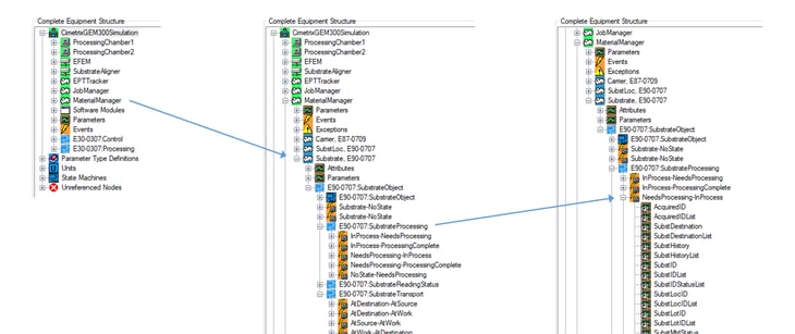
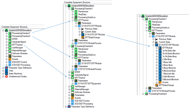
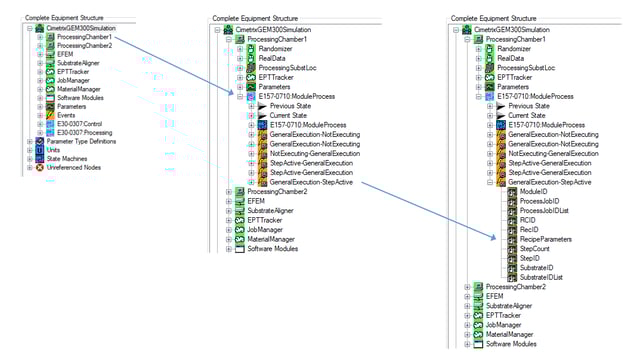
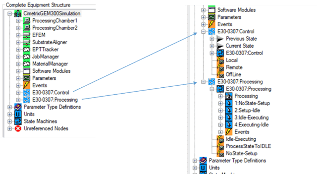
For 300mm equipment with the latest generation of SEMI EDA (Equipment Data Acquisition) interfaces, this means having “good” E120/E125/E164-compliant equipment metadata models as a foundation. On top of this foundation, however, the models must also include the specific parameters, events, state machines, and other items that fully describe the behavior of the equipment according to your unique manufacturing requirements… which can only be achieved by mapping these requirements into specific equipment model elements, and updating your purchase specifications to close whatever gaps you find between what is currently offered by the equipment suppliers and what you really need. Fortunately, we have been through this process a number of times, and can help clarify your manufacturing priorities and translate them directly into updated interface purchase specifications.

Models6_2.png

Admittedly, this may take some time, but remember that you always only get what you are willing to accept. It brings to mind the old adage: “The best time to plant a tree was 20 years ago; the second 

Models6_3.png

best time is today.” 

As another example, if you are part of the embedded control system development team of an equipment supplier, you can anticipate not only increasingly explicit model content requirements, but also more stringent performance and testing requirements for the standard EDA communications interface as your customers raise their reliance on this technology to realize manufacturing competitive differentiation. We at Cimetrix have seen this demand build over the past 18 months, and are well prepared to support you throughout the entire equipment development life cycle.

This article is the sixth and final in the series announced earlier this year in the Models in Smart Manufacturing blog series. From here, we’ll soon begin a new series on advanced EDA applications and benefits based on best practices of the industry leaders – be sure to watch for this early next year!

We look forward to your feedback and to sharing the Smart Manufacturing journey with you.


*The visualizations of equipment metadata model fragments are those produced by the Cimetrix ECCE Plus product (EDA Client Connection Emulator).

Topics: EDA/Interface A, Models in Smart Manufacturing series, Smart Manufacturing/Industry 4.0

Creating a SECS/GEM interface for equipment automation using the Cimetrix CIMConnect toolkit

Posted by Jesse Lopez: Software Engineer on Nov 15, 2017 12:30:00 PM

Adding a SECS/GEM interface to an equipiment is the first step in automation. Without the proper toolset, this can seem like an overwhelming endeavor. The CIMConnect™ toolkit provides developers and integrators with the ability to quickly create a SECS/GEM interface and the power to perfect it.

Purpose
Recently I was introduced to the Cimetrix CIMConnect tookit. I had the opportunity to attend a hands-on client training event. Though my knowledge of SECS/GEM was minimal, within three days, I learned the basics of implementing a SECS/GEM interface using CIMConnect and want to share some highlights of that very positive experience.

CIMConnect
CIMConnect provides a robust software development kit that helps developers implement and manage a SECS/GEM interface from their equipment control application. CIMConnect is always current with the latest version of required SEMI standards which simiplifies the process of producing a GEM-compliant interface. When CIMConnect is installed, it comes with multiple tools that make development and testing straightforward and efficient.

CIMConnect Sample projects
CIMConnect samples provide a functioning example of a SECS/GEM application. Sample projects are available in C#, VB.NET, and C++. I will be referring to the C# sample since that is what I used during training.

This sample provides a “known-good” environment that provides a way to accelerate development by taking care of the essentials. I was able to focus on debugging the scope of what I was working on in my application, rather than questioning the SECS/GEM connectivity aspects.

C# Sample Features

  • Processing Simulation: The sample provides a loop that simulates equipment operation. This includes triggering events and updating variable values. 
  • EMService Initialization: When the Sample is compiled and run, CIMConnect is initialized and GEM communication is started.
  • GEM Operator Controls: GEM communication status is displayed in real time using GEM state machines. Communication can be controlled from the sample’s user interface.
  • Multi-threading Examples: Data is processed in separate threads. This is a good practice and allows the user interface to remain responsive while data is effectively processed asynchronously. 
  • Delayed GEM Communication Initialization: This demonstrates the concept of waiting for the equipment to be ready during initialization. 
  • Trigger Events: Events are triggered from the process simulation loop. As events are triggered, related variables are updated.
  • Get and Set Variable Values: This sample provides multiple examples of programmatically getting and setting variable values of varying data types.
  • Set and Clear Alarms: An example alarm can be set and cleared by toggling a checkbox in the user interface. 
  • Terminal Services: Terminal services provide an example of effective logging by displaying real-time messages to the equipment user interface.
  • Remote Commands: The sample allows the user to start and stop the processing simulation by sending a SECS-II message from the host.

Training process
Training is very interactive; the instructor demonstrates a new topic, and then allows the trainees time to try it out. When presented with a new feature to try out, I found it beneficial to initially create a button or checkbox to ensure the new feature worked. Next, I embedded the feature into the application. Breaking each process into these two steps removes ambiguity and avoids unnecessary debugging.

The pace was set by the client. The instructor was available to provide assistance as needed. Though the training follows a curriculum, each session is custom tailored to the needs of the client who requested the training. 

My Application
I had created a C# application prior to training. My application read in an XML recipe and simulated wafer processing. Having a working application to modify during training was very beneficial, since it simulated a real-world practical implementation.

Adding the SECS/GEM interface
The first step was to initialize CIMConnect. This step was simplified by extracting the Initialization functions from the sample project. Once I could observe that CIMConnect was initialized, I was able to move on to adding the SECS/GEM functionality.

API Calls
My application sends API calls to, and receives call backs from CIMConnect. The API calls were somewhat difficult to understand initially due to the customization each call allows.

Wrapper functions
The sample project provides several useful wrapper functions that implement API calls. The overhead of API calls is handled inside the wrapper. The benefit of using wrapper functions is that the developer can focus on whether the result matches his/her expectations rather than whether the API call is incorrect.

After my success using wrapper functions to call APIs, I started to modify and make my own wrapper functions. Eventually I became comfortable calling the APIs directly.

Equipment Configuration
CIMConnect lets you statically define events, alarms, variables, and other attributes in a configuration file. In my file, I created multiple variables that related to my application. Later I learned that my application could dynamically define items instead. Also, my application could programmatically override configured attributes. I think these features would benefit companies that produce multiple equipment types with slight variances.

Adding Events and Alarms
The first event that I created was to let the host know when a FOUP had landed on the load port. I used the SendCollectionEventWithData() wrapper function to trigger the event and increment a variable I had previously defined in the configuration file. This variable provided me with a count of FOUPs that had landed on the input port.

Using the AlarmSET() and AlarmClear() functions, I created 3 alarms. Since I didn’t have hardware such as an EMO button, I used check boxes to toggle each alarm’s behavior.

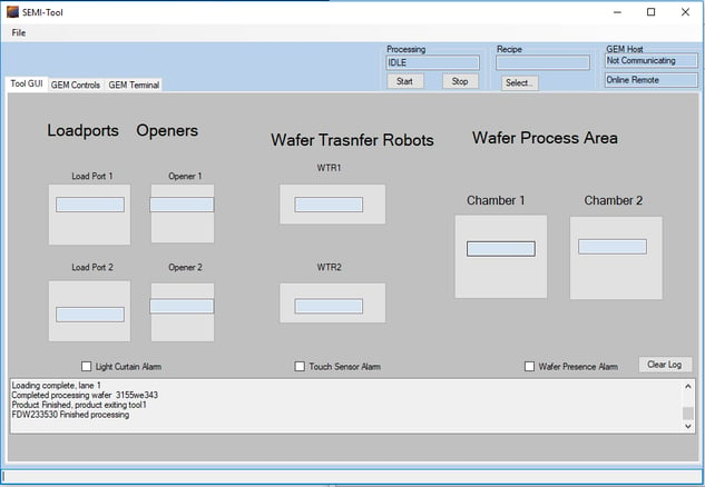
cimconnect_gettingstarted_1.pngMy application with a SECS/GEM interface. 

Developing Using the CIMConnect Control Panel
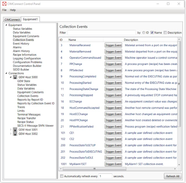
The CIMConnect Control Panel is a graphical user interface utility that provides a way to observe the inner workings of CIMConnect.

During development, I used the control panel frequently. I could watch the alarms status change as I toggled each checkbox in my application. Event history and alarm history provided real-time updates. I could change variable values and trigger events from the control panel and verify results on the host without needing to constantly modify my application.

I watched the GEM communication status change on the control panel as I used my application’s GEM control. I could also change the status on the control panel and watch it change in my application.

cimconnect_gettingstarted_2.png

CIMConnect Control panel 1.15.0

Host Testing with GEM Host Messenger
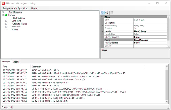
CIMConnect comes with GEM Host Messenger, a host application that allows the user to send and receive SECS-II messages to/from the equipment.

Using GEM Host Messenger, I could easily connect with my application. GEM Host Messenger displays and decodes messages into an easy-to-read format.

I could send S2F21 messages “START” and “STOP” to control processing on my application. It was very satisfying to see my once-standalone application being controlled remotely.

cimconnect_gettingstarted_3.png

Gem Host Messenger 1.0.0

Help Documentation, Tools, and Support
CIMConnect provides an in-depth help file and developer’s guide. I found myself referencing these frequently to get details on different functionality available in the extensive CIMConnect libraries.

Conclusion
CIMConnect allowed me to rapidly develop a SECS/GEM interface and implement it into an already existing program. With CIMConnect training developers unfamiliar with SECS/GEM can learn the basics in as little as 3 working days. Although this was a simple example, CIMConnect has the power and functionality to facilitate projects on any scale.

Find out more
To find out more about CIMConnect and to request a technical product overview or product demo, visit the resources page now.

CIMConnect Resources

Topics: SECS/GEM, Smart Manufacturing/Industry 4.0, Cimetrix Products

SEMICON Taiwan wrap-up

Posted by Alan Weber: Vice President, New Product Innovations on Sep 21, 2017 10:45:00 AM

semicon_Taiwan.jpg

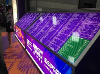
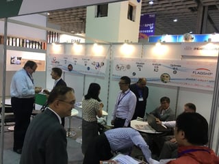
As predicted, Cimetrix had a very busy and fruitful week (September 11-15) in Taiwan. In addition to hosting numerous customers, prospects, and friends at our booth, Cimetrix made multiple technical presentations focused on Smart Manufacturing, both at the show and at the eMDC Conference in Hsinchu. Two of these were jointly presented with Mark Reath of GLOBALFOUNDRIES. Use the links at the bottom of this post if you’d like a copy of this material.

semitaiwan_wrapup1.jpgsemitaiwan_wrapup2.jpg

semitaiwan_wrapup3v1.jpg

In addition to our participation in these technical events, Cimetrix demonstrated the new Cimetrix EDATester™ product to a number of factory customers who now need a validated method for verifying incoming equipment compliance to the SEMI Equipment Data Acquisition (EDA) suite of standards. The timing for this product is ideal, based on the increased rate of adoption for these standards we have seen in Taiwan. 

Given the industry’s current momentum and near-term outlook, the mood in Taiwan is overwhelmingly positive, and the trade show almost had a celebratory quality to it. Fittingly, the Leadership Gala Dinner held Wednesday night was a feast for all the senses, from the food to the entertainment to the array of dignitaries who attended. 

semitaiwan_wrapup4.jpgsemitaiwan_wrapup5v1.jpg

For the second year in a row, President Tsai attended and expressed her gratitude for the industry’s role in advancing the quality of life across the nation and her administration’s unwavering support for its continued prosperity. Dr. Nicky Lu, one of Taiwan’s well-known business and technology icons, was honored with the industry’s most prestigious Leadership Award, and shared his personal perspective on some of the exciting semiconductor-enabled products now in the works. 

semitaiwan_wrapup6edit.jpg

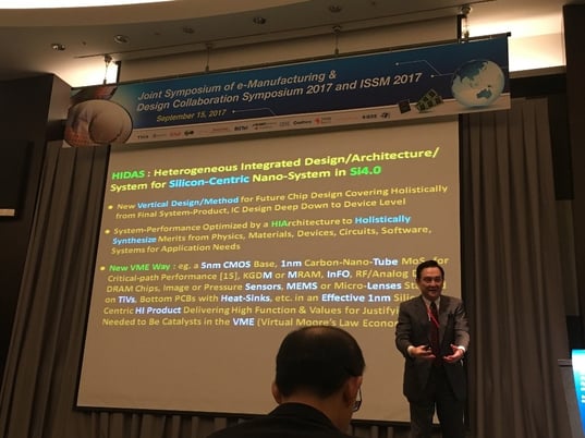
Dr. Lu went into even more depth about semiconductor technology evolution in his keynote address for the eMDC Conference (Joint Symposium of e-Manufacturing & Design Collaboration Symposium 2017 and ISSM 2017) on Friday, outlining a powerful vision that he’s labelled as “HIDAS: Heterogeneous Integrated Design/Architecture/System for Silicon-Centric Nano-System in Si4.0” – if you want to know more, you’ll want to contact him directly!

semitaiwan_wrapup7.jpg

All in all, is was a great week to be in Taiwan, especially since Typhoon Talim decided to take a turn to the north without dampening the spirit of SEMICON. Please contact us with any questions, and we look forward to seeing you at future industry events.

Device Scaling vs. Process Control Scaling: Advanced Sensorization Closes the Gap

Smarter Manufacturing through Equipment Data-Driven Application Design

Smart Manufacturing Requirements for Equipment Capability and Control

Topics: Events, Smart Manufacturing/Industry 4.0

Direct Dashboard Support: Episode 5 in the “Models in Smart Manufacturing” Series

Posted by Alan Weber: Vice President, New Product Innovations on Sep 13, 2017 10:30:00 AM

The definition for a traditional dashboard is fairly simple—“the panel facing the driver of a vehicle or the pilot of an aircraft, containing instruments and controls”—and well understood by anyone with much time behind the wheel.

EDAModels5.1.jpg

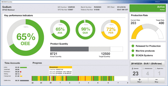
However, information technology dashboards in a business context take a few more words to describe. From Wikipedia, “dashboards often provide at-a-glance views of KPIs (key performance indicators) relevant to a particular objective or business process (e.g., sales, marketing, human resources, or production).” An example of such a dashboard for a single manufacturing process follows.

EDAModels5.2.png

Although only recently popularized by commercial BI (business intelligence) software packages, dashboard-style display technology has been around a long time. Specifically, the PLC (programmable logic controller) industry saw early on that the PC (personal computer) was an ideal user interface platform for machine operators, providing what most would call today an interactive “dashboard” for a piece of equipment or portion of a manufacturing process. PLCs were originally designed as solid-state replacements for the relay panels used for sequence control for small- to medium-sized manufacturing equipment of limited complexity. Over time, they grew in sophistication to include PID (proportional, integral, differential) control capabilities for unit processes across a wide range of industries, and became a vital component of major manufacturing facilities worldwide.

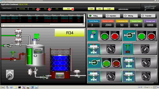
Despite the number of vendors that provided PLCs and the variety of applications they supported, all PLCs shared a common internal architectural feature called an “image register,” which is a section of memory that contains the process and state variables representing the complete status of the machine at any moment. Even though there were initially no industry standards that dictated the exact structure of an image register, they were similar enough that a basic PLC-specific driver was sufficient to map any PLC’s image register into the standard widgets of a dashboard-style operator interface, providing real-time display of process status and sometimes interactive control capabilities. One of the most successful such packages was the Wonderware InTouch software product, shown below in a batch process context.

EDAModels5.3.png

Until recently, the lack of standardization in the embedded control system architectures for semiconductor manufacturing equipment made the implementation of equipment-oriented factory-level dashboards fairly challenging. However, with the advent of the SEMI EDA (Equipment Data Acquisition) standards and, in particular, the increasing fidelity of the equipment models required by these standards, all that has changed. Especially for equipment suppliers who follow the SEMI E164 (EDA Common Metadata) standard, the structure and content of the embedded equipment model are sufficient to provide direct access to most of the parameters and events you’d expect to find in a dashboard. Displaying some equipment KPI's, such as OEE, may require a little additional calculation and perhaps some minimal user input, but the most of information needed to compute these metrics is readily available.

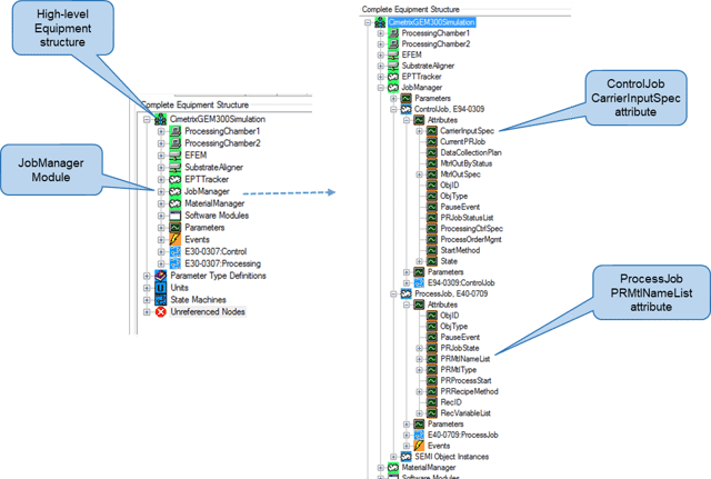
For example, if you want to see the list of jobs active on a piece of equipment, look no further than the JobManager logical element of the metadata model (see below*).

EDAModels5.4.png

If you want to display the material status of a piece of equipment—for example the carriers, lots, and substrates that are present—the MaterialManager logical element contains all of this information.

EDAModels5.5.png

To display the current performance status and recent history of the major equipment modules, use the state information and reason codes in the SEMI E116 (Equipment Performance Tracking) EPTTracker logical elements to achieve this objective.

EDAModels5.6.png

Recipe execution status information for each module capable of processing material is found in the ModuleProcess state machine within the relevant Process Chamber.

EDAModels5.7.png

And finally, if you want to show the current operations status of the equipment as a whole, this information is found in the GEM variables present in the metadata model.

EDAModels5.8.png

You can see from the above examples that despite the lack of standardization in the embedded equipment controller architectures across the semiconductor industry, the information needed in equipment level dashboards is directly provided by the industry standards that define the EDA interfaces. This provides yet another use case for factories to drive for the adoption of these standards.

In addition to the standardized data access, another feature of EDA that makes it ideal for dashboard implementation is its multi-client capability. The software implementing a factory-level dashboard can communicate with many pieces of equipment at once, since the data volume required from any single equipment is small. From the equipment point of view, the dashboard system would appear as a separate client from the other application client(s) with more intense data collection requirements. This separation of clients also means that the dashboard content can be changed easily, since this is accomplished by modifying the relevant DCPs (data collection plans) rather than changing the data collection application itself.

Last but not least, since SEMI E164 standardizes the actual event and parameter names in the metadata model, the DCPs that collect this information can be programmatically generated and activated for all the equipment that is E164-compliant. This represents a significant engineering cost reduction over the conventional methods used to identify, collect, and manage the information required to animate a real-time dashboard.

This article is the fifth in the series recently announced in the Models in Smart Manufacturing Series Introduction posting – be sure to watch for at least one more posting that wraps up this overall theme.

We look forward to your feedback and to sharing the Smart Manufacturing journey with you.


*The visualizations of equipment metadata model fragments are those produced by the Cimetrix ECCE Plus product (EDA Client Connection Emulator).

Topics: Models in Smart Manufacturing series, Smart Manufacturing/Industry 4.0

Traceability Application Support: Episode 4 in the “Models in Smart Manufacturing” Series

Posted by Alan Weber: Vice President, New Product Innovations on Aug 1, 2017 11:15:00 AM

chicken_or_egg.jpg…never mind which came first… do you know where the chicken and the egg came from?
As integrated circuits increasingly find their way into applications for which human and environmental safety are paramount, the regulatory requirements related to product traceability become ever more stringent. For example, the automotive industry already requires that a device maker be able to provide a full manufacturing process history within 48 hours of a request for certain kinds of products, but this only scratches the surface of what’s to come in the growing markets for autonomous vehicles and their supporting public infrastructure, aircraft components, medical implants and diagnostic systems, and the like.

semiconductor_manufacturingThe good news in all this is that the latest semiconductor manufacturing equipment interface standards include enough information about the product being built and the processes used at each step along the way to directly support these traceability requirements with little or no custom software. Specifically, the SEMI Equipment Data Acquisition (EDA) suite of standards (also known as “Interface A”) defines the components of an explicit equipment model that can represent this information, and the SEMI E164 (EDA Common Metadata) standard goes so far as to specify the actual structure and naming conventions for the required components.

Before getting deeper into the specifics, let’s step back and define “traceability” in this context. According to ISO 9000 (Quality management systems – Fundamentals and vocabulary), the term means “the ability to trace the history, application or location of an entity by means of recorded identifications.” 

In a wafer fabrication facility, this definition covers a broad range of capabilities. The most basic interpretation could be satisfied by simply having an ordered list of the manufacturing equipment visited by each wafer (substrate) during its 3-month journey through the fab. As long as the manufacturer keeps a record of which substrate each assembled die came from (which most do), the required documentation could be generated from information contained in the MES (Manufacturing Execution System) and its associated scheduling/dispatching system. 

Symptoms_Problems_Cause_tree

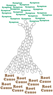
However, at the other end of the spectrum, the traceability requirement may include not only the list of equipment visited, but also the recipe used at each equipment, the precise timing of wafer movement and process modules visited within the equipment, values of any adjustable recipe parameters and/or equipment constants that affect process behavior, batch identification and status information for any consumables used during the process, usage counts for any fixtures involved, operator interactions (if any), and so on. The reason for this level of detail is to enable the failure analysis engineers to identify the potential root causes for any field failures, and then determine what other devices in the field may be susceptible to similar failure conditions for product recall purposes.

To be sure, much of this information could be assembled after-the-fact from the various data bases maintained by the equipment and process engineering and yield management systems present in most modern wafer fabs, but this process can be complex, time-consuming, and error-prone. A better approach would be to generate the most commonly needed traceability records on-the-fly directly from information available in the equipment... and this is where the newest EDA standards enter the picture. 

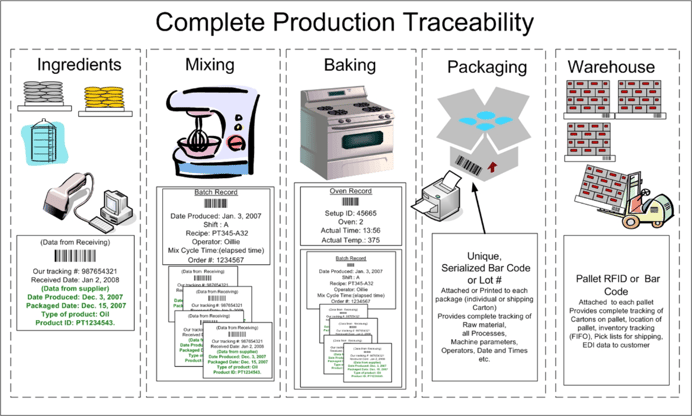
By analogy, let’s look at an intuitive example: a commercial cake baking enterprise. Even for a relatively simple (compared to semiconductor manufacturing) production process, full traceability requires information from the raw materials suppliers through the manufacturing process to packaging and finished goods warehousing. You can see in the picture below that material, recipe, and equipment setup information is included in the records produced.

Complete Production Traceability

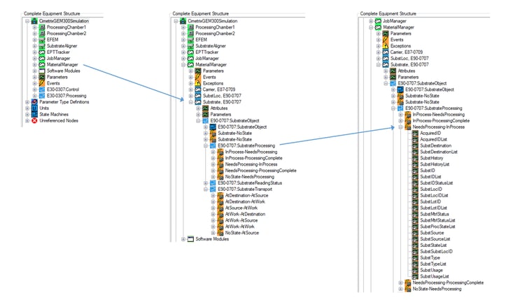
In a unit of semiconductor manufacturing equipment with an E164-compliant interface, these types of information appear in various sections of the equipment metadata model. Specifically, material-related information is captured in the “Material Manager” logical component, shown in expanded view below* to highlight the state transition events and parameter data available for each substrate during its transportation and processing in the equipment.

Material_Manager_component

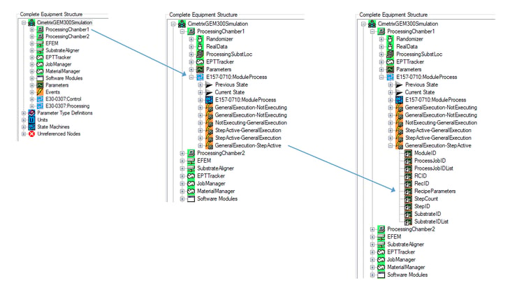
Recipe-related information is found in the physical modules responsible for substrate processing (“ProcessingChamber1” and “ProcessingChamber2” in the example below), within the “E157-0710:ModuleProcess” state machine, dictated by the SEMI E157 (Module Process Tracking) standard and required by E164. Note the rich list of context information available at every recipe step, including the RecipeParameters array, in the expanded model excerpt below. RecipeParameters_arrayTaken together, the timing and parameter data from these two sections of the equipment model supply most of the information required for full wafer fab traceability. Moreover, since SEMI E164 actually standardizes the event and parameter names in the model, the DCPs (data collection plans) that collect this information can be programmatically generated and activated for all the equipment that is E164-compliant. This represents a significant engineering cost reduction over the conventional methods used to identify, collect, and manage this information. The figure below is one visualization of such a DCP.DCP_Visualization

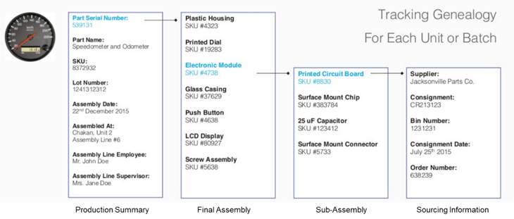
When extended beyond individual devices to circuit boards, modules, and completed parts (see the example below for an automobile speedometer), these requirements require even more bookkeeping… but that’s a topic for another day!automobile_speedometer

This article is the fourth in the series recently announced in the Models in Smart Manufacturing Series - Introduction, be sure to watch for subsequent postings that will expand on this theme. 

We look forward to your feedback and to sharing the Smart Manufacturing journey with you.


*The visualizations of equipment metadata model fragments and DCP contents are those produced by the Cimetrix ECCE Plus product (EDA Client Connection Emulator).

Topics: EDA/Interface A, Models in Smart Manufacturing series, Smart Manufacturing/Industry 4.0

Precision Data Framing during Process Execution – Tricks of the Trade: Episode 3 in the “Models in Smart Manufacturing” Series

Posted by Alan Weber: Vice President, New Product Innovations on Jun 27, 2017 11:30:00 AM

…or how to move away from “just in case” data collection...

It’s a common process engineering request of the manufacturing IT folks: “Please collect as much data as you can during this process, and we’ll figure out what’s important later.” And this approach has worked fairly well up to this point. However, with 10nm (and below) production on the horizon, coupled with the desire to sample key parameters at ever-increasing rates, the amount of on-line data storage required to support this approach could skyrocket… to say nothing of the difficulty in sifting through all that data to extract the real information you wanted in the first place.

Models3.1.jpgModels3.2.jpg

Fortunately, you don’t have to look very far into the SEMI EDA (Equipment Data Acquisition) standards (also known as “Interface A”) to find an excellent solution alternative. The portion of the standard equipment metadata model (specified by SEMI E164 – EDA Common Metadata) that deals with process execution (SEMI E157 – Process Execution Tracking) combined with the conditional triggering features of Trace Requests (SEMI E134 – Data Collection Management) enables a process engineer to precisely collect the right data at the right time at the right frequency without over-burdening the equipment or factory systems by collecting and storing less important data at the highest rates. 

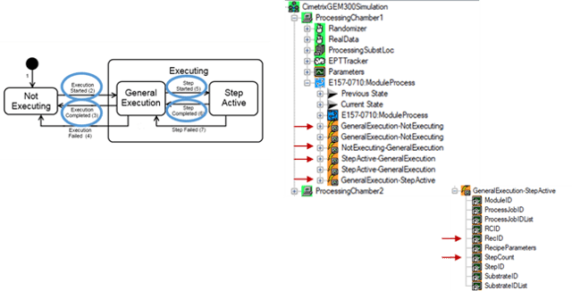
Let’s look at an example. The key state machine called for in the E157 standard (see figure below*) has 2 major states (NOT EXECUTING and EXECUTING) with intuitive transition events defined between them (Execution Started, Execution Completed, and Execution Failed). If you only care about tracking the overall execution time of the process recipes on a given tool, then a single DCP (Data Collection Plan) with a pair of Event Requests on the Started and Completed events is all you need. The difference in the timestamps of the corresponding Event Reports provides the necessary information. 

Models3.3.png

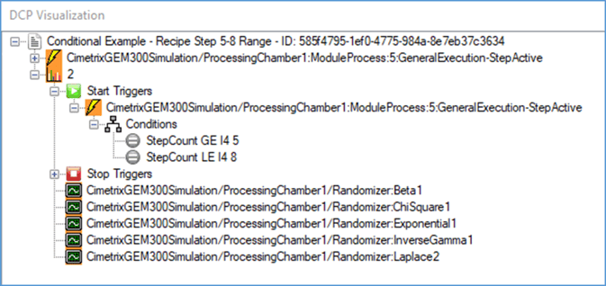
However, if you want to monitor a baseline set of equipment performance parameters at a low frequency (say, 1 Hz) throughout the recipe, and collect the key parameters for analyzing process behavior at a higher frequency (50 Hz) during the most critical process steps (5 through 8), you would use a DCP with multiple Trace Requests triggered by the Step Started and Step Completed transition events between the two sub-states (GENERAL EXECUTION and STEP ACTIVE) of the EXECUTING state. Furthermore, you would use the conditional triggering feature of the Freeze II version of the EDA standards (SEMI E134-0710 or later) to produce Trace Reports only during the critical process steps. The figure below is one visualization* of such a DCP.

Models3.4.png

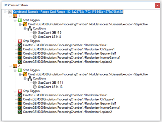
You may have noticed from this example that multiple triggering conditions are ANDed together to determine whether or not to collect the data and generate a Trace Report. But how do you handle the situation in which OR functionality is needed to produce the desired result, for example, in the case that multiple sets of recipe steps are considered critical (say, steps 5-8 and steps 11-13)?

This is where you can use one of the “tricks of the trade.” Simply define multiple Trace Requests with different sets of ANDed conditions to cover the range of ORed situations. For the case above, you would need two Trace Requests: one for each critical set of contiguous recipe steps (see visualization below).

Models3.5.png

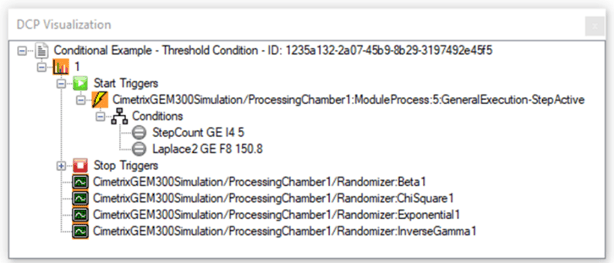
Note finally that you can also apply comparison operators to analog values to trigger Trace Requests, which may be especially useful to sample specific parameters when some value crosses an important threshold. 

Models3.6.png

Taken together, these techniques are sometimes called “data framing,” which is an important tool in the controlling the scope of factory data explosion that will soon be upon us. 

This article is the third in our Models in Smart Manufacturing series – be sure to watch for subsequent postings that will expand on this theme.

We look forward to your feedback and to sharing the Smart Manufacturing journey with you.

*The visualizations of equipment metadata model fragments and DCP contents are those produced by the Cimetrix ECCE Plus product (EDA Client Connection Emulator).


Topics: EDA/Interface A, Models in Smart Manufacturing series, Smart Manufacturing/Industry 4.0

Cimetrix International, Inc., Taiwan Branch美商矽美科國際股份有限公司台灣分公司

Posted by Michael Lee; Country Manager Taiwan on Jun 14, 2017 11:30:00 AM

Michael Lee of Cimetrix announces the Taiwan Office Opening. Read now in Chinese or English.

當工廠的產品需要加入更多的功能,交期需要更迅速,工資需要提高,智慧製造提供了一個最好的解決方案。美商矽美科所提供的工廠自動化軟體,提升了聯繫工廠主機與設備控制在半導體、電子組裝、太陽能模組、發光二極體等相關的電子產業。我們在工業界領先的產品,給予客戶用較低的成本、客制化生產、迅速上市,並集中在成功實行工具控制與SEMI標準。

我很榮幸在今年二月進入美商矽美科。我們和知名的半導體廠商、印刷電路板商、設備商、機器人製造商等客戶合作,而這些公司給予我們最佳的評價。矽美科帶給他們一個極為經濟、有效率和聯繫良好的方案。我們提供了CIMConnect, EDA等產品來滿足廠商不同的需求。

Cimetrix Diagram

矽美科台灣辦公室將在5月31日開幕。我們感謝我們的客戶跟合作夥伴。我們將帶給你更方便、更熱情的服務,並展望在台灣及中國服務更多半導體、電路板和面板廠商。 

台灣銷售辦事處:

Cimetrix International, Inc., Taiwan Branch
美商矽美科國際股份有限公司台灣分公司4F., No.301,
Sec. 2, Tiding Blvd,
Taipei 114, Taiwan, R.O.C.
中華民國台灣台北市堤頂大道二段301號4樓 114

電話: +886-926395649
聯絡人:Michael Lee


When it comes to adding product functionality, shortening delivery time, or increasing wages, smart manufacturing provides the best solution. Cimetrix provides factory automation software which increases host connectivity and equipment control for semiconductor, electronics assembly, photovoltaic, LED, and related electronics industries. Our industry-leading products focus on successful implementation of tool control and SEMI connectivity standards to enable faster time-to-market, increased customization, and decreased total cost of ownership.

I was honored to join the Cimetrix team in February earlier this year. We work with major semiconductor companies, PCB manufacturers, equipment vendors, robotics specialists and more. I was happy to know that everyone I've worked with has high praise for this company.  Cimetrix can bring their customers and clients connected products that are efficient and cost-effective. Cimetrix offers a large portfolio of products such as CIMConnect, HostConnect, and EDA to meet the various needs of their customers.

blog diagram.png

The Cimetrix International, Inc., Taiwan Branch officially opened on May 31, 2017. Thanks to all our partners and customers. We hope to continue to bring you convenient and passionate service. I am looking forward to working with all our current and future customers in Taiwan and China! 

Contact Us:
Cimetrix International, Inc., Taiwan Branch
4F., No. 301,
Sec. 2, Tiding Blvd,
Taipei 114, Taiwan, R.O.C.

Phone: +886-926395649
Contact: Michael Lee

Topics: Doing Business with Cimetrix, Cimetrix Company Culture, Global Services, Smart Manufacturing/Industry 4.0

Implementing GEM on your Manufacturing Equipment

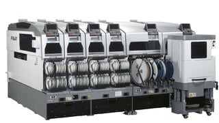
Fuji SMT machine 3.jpgAs an OEM, implementing GEM on your equipment can seem like a daunting task. However, as GEM gains popularity in your industry, your customers may start requiring your equipment to be “GEM Compliant”.
So, what does it take to implement GEM on your equipment and become “GEM Compliant”? To answer this question, let’s first understand GEM.

Officially titled the “Generic Model for Communication and Control of Manufacturing Equipment,” GEM is a SEMI standard (E30), which defines standard methods to communicate with host software for monitoring and/or controlling purposes. Essentially, GEM provides a common language for a host system to communicate with the various equipment in a factory. 

Next, let’s understand why customers are demanding your equipment to be GEM Compliant.

As industry trends such as Industry 4.0, Smart Factory, and Big Data drive data exchange and process automation in manufacturing, factories desire to connect each machine to their network for data collection and control. Essentially, factory equipment is added to the “Internet of Things” – also called IIOT - Industrial Internet of Things.  

GEM is a powerful enabler for factories to implement these industry trends. A factory no longer needs to develop disparate/custom interfaces to communicate with different equipment types. A factory can develop common applications to communicate to all equipment via a single common GEM protocol. Originally, GEM was widely adopted in the Semiconductor Front End industry followed later by the Photovoltaic and LED industries. Recently the PCB industry selected GEM as their standard. And GEM is quickly gaining adoption in other electronics industries such as Semiconductor Back End, Flat Panel Display, and Surface Mount Technology.

By connecting GEM equipment, factories can immediately experience operational benefits. Examples of such benefits are:…

  • Ensure recipe (aka process program) correctness and track when recipes are changed/revised
  • Monitor equipment performance to calculate Overall Equipment Effectiveness (OEE) metrics
  • Gather real-time data variables to implement Statistical Process Control (SPC) for key processes
  • Broadcast equipment alarms to immediately notify personnel when equipment requires assistance
  • Collect equipment parameters to drive preventative maintenance plans

Now that we understand GEM, we can explain the term “GEM Compliance”.

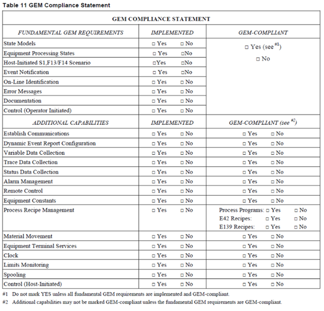
GEM Compliance is defined in the SEMI E30 GEM standard. To be “GEM Compliant” means your equipment implements a specific set of capabilities called “Fundamental GEM Requirements”. Your equipment may also implement optional features called “Additional Capabilities”. The SEMI E30 standard provides a list of all GEM features, as listed below.

gem compliance.png
Per Table 11 Section 8.4.3. of the document "SEMI E30-0307E2"

So, how do you become “GEM Compliant”?

As mentioned above, to be GEM compliant, the equipment must implement the eight capabilities listed under Fundamental GEM Requirements. If one of the fundamental capabilities is not implemented, then you cannot say the equipment is GEM compliant.  However, each capability listed under Additional Capabilities is optional. Implementing GEM also means implementing the other SEMI standards that GEM is based on including: E4 (SECS-I), E5 (SECS-II)E37(HSMS), E37.1 (HSMS-SS). In addition, depending on your industry, there may be additional standard to adhere to.

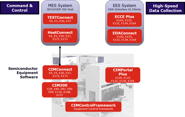
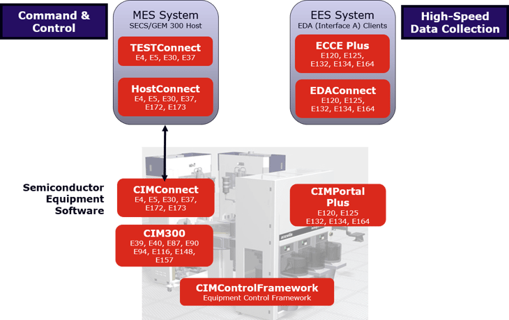
All-in-all, there are 100’s of standards pages filled with requirements and implementation information. Reading and implementing all the requirements defined in those standards may require extensive time. However, toolkits such as our CIMConnectTM product greatly reduce the number of people and time needed to implement a fully GEM compliant interface.

A simple GEM interface that only implements the Fundamental capabilities can be completed relatively quickly. However, a toolkit like CIMConnect enables a small team of one or two people to implement a fundamental interface in even less time. CIMConnect reduces time by implementing the GEM features that are common to all equipment, and providing API to implement the capabilities unique to your equipment. Toolkits also provide several utilities to help become GEM compliant. For example, one of the fundamental GEM requirements is to provide a GEM interface manual with each equipment. CIMConnect provides a template and a documentation builder to help create your manual. These tools reduce the time to create a GEM interface manual from weeks to hours. With products like CIMConnect, a more complex GEM interface can be implemented in just a couple weeks.

Whether you use CIMConnect or an in-house solution, the process for developing a GEM interface is roughly the same:

  • Define and Document GEM interface
  • Implement GEM interface
  • Test GEM interface
  • Customer accepts GEM interface

Defining and documenting the GEM interface of the equipment should be first because it helps to reduce feature creep, keep the project on course, and ensure the project is completed on time. Implementing the GEM interface is often the largest part of the process. Since no two equipment are alike, programming is required to customize the GEM interface for your equipment. It is common to test the GEM interface as each feature is implemented. Testing ensures your GEM implementation is compliant with the GEM standard and is defect free. Some use a completely manual testing process that can take weeks, but we recommend creating automated tests that can be built with our Cimetrix HostConnectTM product. Automated testing allows defects to be detected and fixed quickly; preventing unexpected development costs down the line. Once you believe your interface is free of defects, it’s time to get acceptance from your customer.

To ensure continued success, it is important for your GEM product supplier to provide training and on-going product support. Proper training and support from your GEM supplier allows you to provide continuous support to your customers.

Congratulations – you are on your way to being able to make your equipment “GEM Compliant”.  You can successfully meet your customers’ requirements while keeping your team’s resources on their core competency. 

Topics: SECS/GEM, Smart Manufacturing/Industry 4.0, SMT/PCB/PCBA

European Advanced Process Control and Manufacturing Conference XVII: Retrospective and Invitation

Posted by Alan Weber: Vice President, New Product Innovations on May 17, 2017 11:30:00 AM

APC.jpgCimetrix participated in the recent European Advanced Process Control and Manufacturing (apc|m) Conference, along with over 150 control professionals across the European and global semiconductor manufacturing industry. The conference was held in Dublin, a lively city on the east coast of Ireland which features a charming juxtaposition of old and new and is home to 1.2 million of the friendliest and most talkative people on the planet! 

APC_2017_1.jpg

Of course, one of Ireland’s greatest “natural resources” may also contribute to their fine spirits…

APC_2017_2.jpg

This conference, now in its 17th year and organized by Silicon Saxony, is one of only a few global events dedicated to the domain of semiconductor process control and directly supporting technologies. This year’s attendance was up from that of the three previous years, a clear indication that this area continues to hold keen interest for the European high-tech manufacturing community. Moreover, the participants represented all links in the semiconductor manufacturing value chain, from universities and research institutes to component, subsystem, and equipment suppliers to software product and services providers to semiconductor IDMs and foundries across a wide spectrum of device types to industry trade organizations – something for everyone.

APC_2017_3-1.jpg

The local sponsor for the conference was Intel, which is the largest private-sector investor in the Irish economy and one of its biggest employers. In addition to excellent logistics support, Intel hosted a lovely evening of fine food and local entertainment at the world-renowned Trinity College.

APC_2017_4.1.pngAPC_2017_5.png

As in many prior years, Cimetrix was privileged to present at this conference. Alan Weber delivered a talk entitled “Smarter Manufacturing with SEMI Standards: Practical Approaches for Plug-and-Play Application Integration.” This topic was well aligned with one of the key themes of this year’s event, but stressed the point that our industry already has at its disposal many of the tools, techniques, and enabling standards required for Smart Manufacturing. Specifically, the presentation illustrated how the new SEMI E172 SECS Equipment Data Dictionary (SEDD) standard could be used to document an equipment’s GEM interface in way that provided much of the same hierarchical structure and context information inherent in the latest generation of EDA metadata models (SEMI E120, E125, and E164). If you want to know more, feel free to download a copy of the entire presentation from our web site.

In addition to Smart Manufacturing, recurring themes of the presentations included:

  • The IoT (Internet of Things) and interesting applications for all these “things” (e.g., most new drugs depend on a “smart delivery device” to be used safely and effectively)
  • Decision-driven data collection strategies (vs. “just in case” approaches)
  • Automated analysis, automated decision making, artificial intelligence, and other forms of machine learning
  • The evolution from reactive systems to predictive systems, or in Gartner’s terms, using data to move from hindsight to insight to foresight 
  • The increasing use eOCAP techniques (electronic aids and workflow engine support for Out-of-Control Action Plan execution) 
  • And, last but certainly not least, connectivity standards and technologies as key enablers of much of the above

The agenda also featured keynotes and invited talks from a variety of sources, namely:

  • Bosch – Success Factors for Semiconductor Manufacturing in High-Cost Locations
  • Intel – IoT’s Connected Devices and Big Data Analytics: the Opportunities and Challenges in Semiconductor Manufacturing
  • ST Microelectronics – FDC Control: the Loop Between Standardization and Innovation
  • IBM Research – Automating Analytics for Cognitive IoT 
  • Rudolph Technologies – Smart Manufacturing
  • Applied Materials – Advancements in FDC: Reducing False Alarms and Optimizing Model and Limits Management

The insights gained from these and the other 30+ presentations are too numerous to list here, but in aggregate, they provided an excellent reminder of how relevant semiconductor technology has become for our comfort, sustenance, safety, and overall quality of life. 

This conference and its sister conference in the US are excellent venues to understand what manufacturers do with all the data they collect, so if this topic piques your interest, be sure to put these events on your calendar in the future. In the meantime, if you have questions about any of the above, or want to know how equipment connectivity and control fit into the overall Smart Manufacturing landscape, please contact us!

Topics: Semiconductor Industry, EDA/Interface A, Events, Smart Manufacturing/Industry 4.0

Exposing Hidden Capacity through Material Tracking: Episode 2 in the “Models in Smart Manufacturing” Series

Posted by Alan Weber: Vice President, New Product Innovations on May 9, 2017 11:38:00 AM

“Do you know where your wafers are? Are you SURE?”

This adaptation of the famous public service announcement is as relevant for semiconductor process and industrial engineers as it was (and still is) for responsible parents. Given the ever-present productivity and profitability pressures in modern wafer fabs, it is essential to know the location and status of all product material at all times, because this information drives the scheduling and material delivery systems that provide competitive advantage for the world’s leading manufacturers. Until recently, material visibility at the lot/FOUP level was sufficient for this purpose, but this is no longer the case. 

Where_are_you.jpg

As production managers look for ways to squeeze more capacity out of their existing capital equipment, they realize that a deeper understanding of the wafer processing sequence within a particular tool type may provide opportunities to shorten the its overall lot processing time and increase the amount of material that can be processed simultaneously.  The first improvement results from identifying and eliminating unnecessary “wait” states* that individual wafers (or groups of wafers) may experience because of sub-optimal internal material handling, shared resource constraints, mis-calibrated subcomponents, poor recipe design, or a combination of these and other factors. The second improvement results from starting the next lot scheduled for a given tool as soon as all the wafers in the current lot have cleared the first stage of the process. This technique is sometimes called “cascading” or “continuous processing,” and applies to an increasing number of multi-chamber equipment types.

When applied to all the critical “bottleneck” tools in a factory, you can imagine what the resulting benefits would be for cycle time and capacity. Estimates of 3-5% improvement in these KPIs are not unrealistic.

Easy to say, right? But not so easy to implement? Perhaps not as daunting as you think…

The information required to track the precise location, movement, and status of individual wafers in semiconductor manufacturing equipment is most likely available for most equipment types in the form of “events” that chronicle the behavior of substrates, substrate locations, process chambers, aligners, wafer handling robots, and the other equipment components that affect wafer processing. What’s missing is a standard model that unifies this information across multiple equipment types, which would greatly simplify the data collection and analysis software required to implement a robust, generic material tracking system.

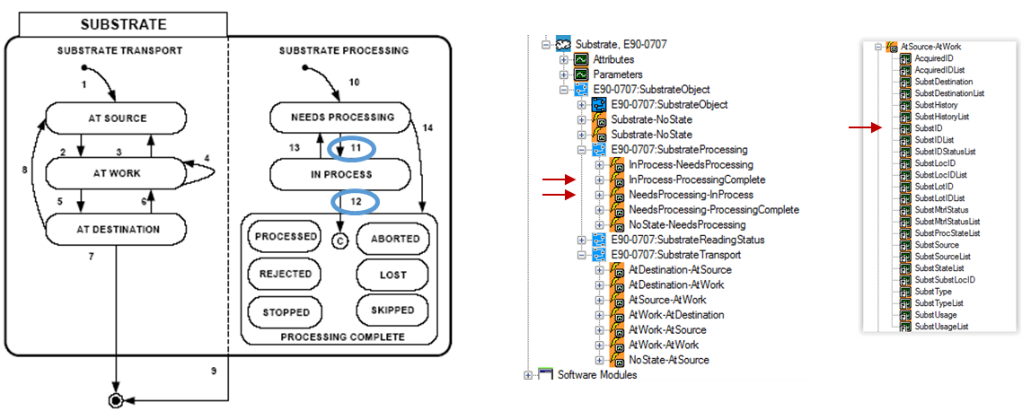
Here, too, the industry standards are actually ahead of today’s “state of the practice.” For example, the SEMI E90 “Substrate Management” and E157 “Specification for Module Process Tracking” standards define all the state machines, transition events, and associated context parameter data necessary to create a detailed Gantt chart of individual wafer movement and processing from start to finish, and allocate each contiguous time segment to its associated “active” or “wait” time element. The insights gained from this sort of visualization point directly to the opportunities cited above for improved tool control and factory scheduling.

Excerpts of these standards, a treeview representation of their respective models, and examples of the potential tracking displays are shown below.

Models_1.png

Models_2.pngModels_3.png

Models_4.png

Note that the SEMI E164 “Specification for EDA Common Metadata” calls for the inclusion of E90, E157, and a list of other GEM300 standards in the EDA equipment metadata model, so any E164-compliant equipment would directly and completely support such a material tracking application.

This article is only the second in the series recently announced in the Models in Smart Manufacturing Series Introduction posting – be sure to watch for subsequent postings that will expand on this theme.

We look forward to your feedback and to sharing the Smart Manufacturing journey with you.

*The list of potential “wait” states for semiconductor manufacturing has now been precisely defined and standardized as SEMI E168 “Specification for Product Time Measurement.” The standard also describes how they can be calculated using a specific set of standard material movement events commonly used in 300mm manufacturing equipment.

Topics: EDA/Interface A, Models in Smart Manufacturing series, Smart Manufacturing/Industry 4.0