Industry News, Trends and Technology, and Standards Updates

Conclusions and Call to Action: 6th and Final Episode in the “Models in Smart Manufacturing” Series

Posted by Alan Weber: Vice President, New Product Innovations on Dec 1, 2017 11:00:00 AM

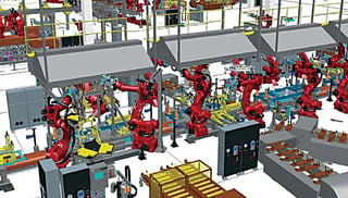
Over the past several months, we’ve highlighted the importance of explicit and standardized models in the context of equipment communications interfaces and some of the “smart” factory applications they support. The manufacturing stakeholders impacted by these applications run the gamut from process, equipment, maintenance, and industrial engineering to production operations to traceability regulatory compliance… yet these only scratch the surface.
Mfg_Model3.jpg

The question you may be asking now is “So what?” or “What should I do with this information?” The answer to these important questions depends on your company and your role. 

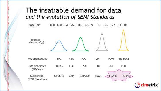
For example, if you’re part of a semiconductor manufacturing enterprise in today’s market environment, you know that you can probably sell every good device you make, so there is intense pressure to simultaneously maximize product quality, volume, and [factory and engineering] productivity–a perfect storm. Since lead times for new equipment needed for capacity expansion are at all-time highs, this means getting as much as you can out of your existing facilities while waiting for new deliveries. New applications to monitor and improve these KPIs are being developed continuously, but the one thing they have in common is a reliance on detailed, high quality, easily accessible and interpretable equipment data.
Models6_1.png

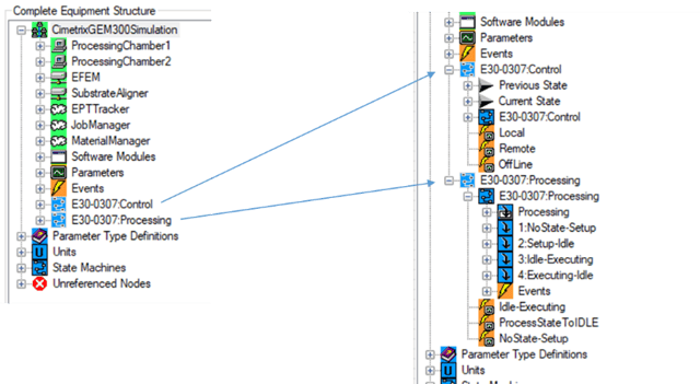
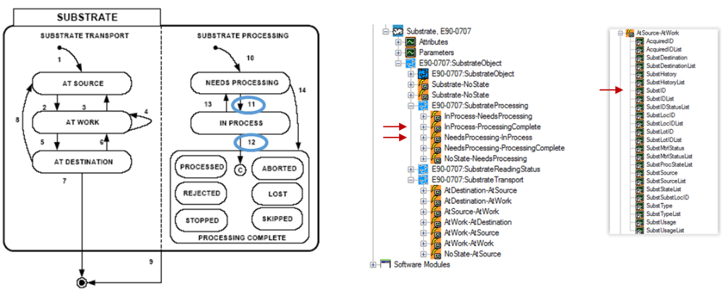
For 300mm equipment with the latest generation of SEMI EDA (Equipment Data Acquisition) interfaces, this means having “good” E120/E125/E164-compliant equipment metadata models as a foundation. On top of this foundation, however, the models must also include the specific parameters, events, state machines, and other items that fully describe the behavior of the equipment according to your unique manufacturing requirements… which can only be achieved by mapping these requirements into specific equipment model elements, and updating your purchase specifications to close whatever gaps you find between what is currently offered by the equipment suppliers and what you really need. Fortunately, we have been through this process a number of times, and can help clarify your manufacturing priorities and translate them directly into updated interface purchase specifications.
Models6_2.png

Admittedly, this may take some time, but remember that you always only get what you are willing to accept. It brings to mind the old adage: “The best time to plant a tree was 20 years ago; the second 

Models6_3.png

best time is today.” 

As another example, if you are part of the embedded control system development team of an equipment supplier, you can anticipate not only increasingly explicit model content requirements, but also more stringent performance and testing requirements for the standard EDA communications interface as your customers raise their reliance on this technology to realize manufacturing competitive differentiation. We at Cimetrix have seen this demand build over the past 18 months, and are well prepared to support you throughout the entire equipment development life cycle.

This article is the sixth and final in the series announced earlier this year in the Models in Smart Manufacturing blog series. From here, we’ll soon begin a new series on advanced EDA applications and benefits based on best practices of the industry leaders – be sure to watch for this early next year!

We look forward to your feedback and to sharing the Smart Manufacturing journey with you.


*The visualizations of equipment metadata model fragments are those produced by the Cimetrix ECCE Plus product (EDA Client Connection Emulator).

Topics: EDA/Interface A, Models in Smart Manufacturing series, Smart Manufacturing/Industry 4.0

Direct Dashboard Support: Episode 5 in the “Models in Smart Manufacturing” Series

Posted by Alan Weber: Vice President, New Product Innovations on Sep 13, 2017 10:30:00 AM

The definition for a traditional dashboard is fairly simple—“the panel facing the driver of a vehicle or the pilot of an aircraft, containing instruments and controls”—and well understood by anyone with much time behind the wheel.

EDAModels5.1.jpg

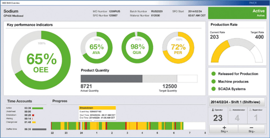
However, information technology dashboards in a business context take a few more words to describe. From Wikipedia, “dashboards often provide at-a-glance views of KPIs (key performance indicators) relevant to a particular objective or business process (e.g., sales, marketing, human resources, or production).” An example of such a dashboard for a single manufacturing process follows.

EDAModels5.2.png

Although only recently popularized by commercial BI (business intelligence) software packages, dashboard-style display technology has been around a long time. Specifically, the PLC (programmable logic controller) industry saw early on that the PC (personal computer) was an ideal user interface platform for machine operators, providing what most would call today an interactive “dashboard” for a piece of equipment or portion of a manufacturing process. PLCs were originally designed as solid-state replacements for the relay panels used for sequence control for small- to medium-sized manufacturing equipment of limited complexity. Over time, they grew in sophistication to include PID (proportional, integral, differential) control capabilities for unit processes across a wide range of industries, and became a vital component of major manufacturing facilities worldwide.

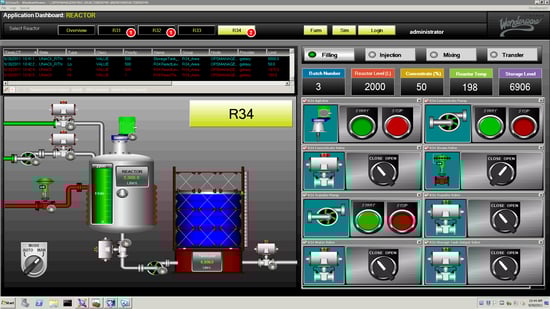
Despite the number of vendors that provided PLCs and the variety of applications they supported, all PLCs shared a common internal architectural feature called an “image register,” which is a section of memory that contains the process and state variables representing the complete status of the machine at any moment. Even though there were initially no industry standards that dictated the exact structure of an image register, they were similar enough that a basic PLC-specific driver was sufficient to map any PLC’s image register into the standard widgets of a dashboard-style operator interface, providing real-time display of process status and sometimes interactive control capabilities. One of the most successful such packages was the Wonderware InTouch software product, shown below in a batch process context.

EDAModels5.3.png

Until recently, the lack of standardization in the embedded control system architectures for semiconductor manufacturing equipment made the implementation of equipment-oriented factory-level dashboards fairly challenging. However, with the advent of the SEMI EDA (Equipment Data Acquisition) standards and, in particular, the increasing fidelity of the equipment models required by these standards, all that has changed. Especially for equipment suppliers who follow the SEMI E164 (EDA Common Metadata) standard, the structure and content of the embedded equipment model are sufficient to provide direct access to most of the parameters and events you’d expect to find in a dashboard. Displaying some equipment KPI's, such as OEE, may require a little additional calculation and perhaps some minimal user input, but the most of information needed to compute these metrics is readily available.

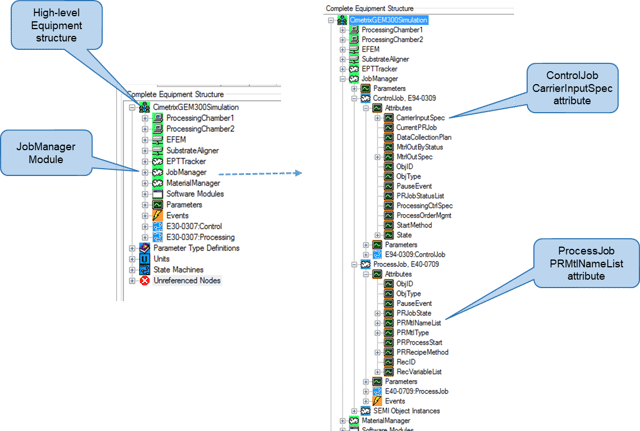
For example, if you want to see the list of jobs active on a piece of equipment, look no further than the JobManager logical element of the metadata model (see below*).

EDAModels5.4.png

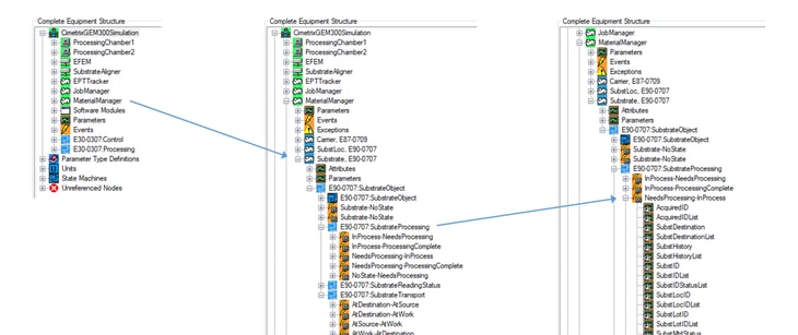
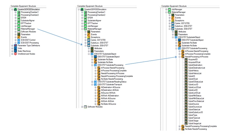
If you want to display the material status of a piece of equipment—for example the carriers, lots, and substrates that are present—the MaterialManager logical element contains all of this information.

EDAModels5.5.png

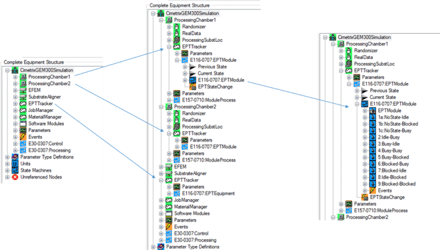
To display the current performance status and recent history of the major equipment modules, use the state information and reason codes in the SEMI E116 (Equipment Performance Tracking) EPTTracker logical elements to achieve this objective.

EDAModels5.6.png

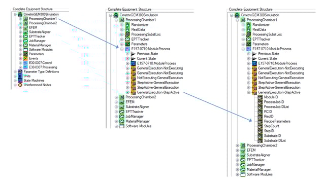
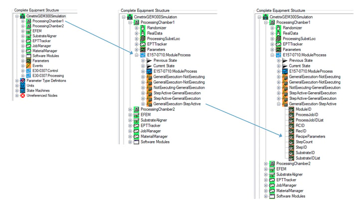
Recipe execution status information for each module capable of processing material is found in the ModuleProcess state machine within the relevant Process Chamber.

EDAModels5.7.png

And finally, if you want to show the current operations status of the equipment as a whole, this information is found in the GEM variables present in the metadata model.

EDAModels5.8.png

You can see from the above examples that despite the lack of standardization in the embedded equipment controller architectures across the semiconductor industry, the information needed in equipment level dashboards is directly provided by the industry standards that define the EDA interfaces. This provides yet another use case for factories to drive for the adoption of these standards.

In addition to the standardized data access, another feature of EDA that makes it ideal for dashboard implementation is its multi-client capability. The software implementing a factory-level dashboard can communicate with many pieces of equipment at once, since the data volume required from any single equipment is small. From the equipment point of view, the dashboard system would appear as a separate client from the other application client(s) with more intense data collection requirements. This separation of clients also means that the dashboard content can be changed easily, since this is accomplished by modifying the relevant DCPs (data collection plans) rather than changing the data collection application itself.

Last but not least, since SEMI E164 standardizes the actual event and parameter names in the metadata model, the DCPs that collect this information can be programmatically generated and activated for all the equipment that is E164-compliant. This represents a significant engineering cost reduction over the conventional methods used to identify, collect, and manage the information required to animate a real-time dashboard.

This article is the fifth in the series recently announced in the Models in Smart Manufacturing Series Introduction posting – be sure to watch for at least one more posting that wraps up this overall theme.

We look forward to your feedback and to sharing the Smart Manufacturing journey with you.


*The visualizations of equipment metadata model fragments are those produced by the Cimetrix ECCE Plus product (EDA Client Connection Emulator).

Topics: Models in Smart Manufacturing series, Smart Manufacturing/Industry 4.0

Traceability Application Support: Episode 4 in the “Models in Smart Manufacturing” Series

Posted by Alan Weber: Vice President, New Product Innovations on Aug 1, 2017 11:15:00 AM

chicken_or_egg.jpg…never mind which came first… do you know where the chicken and the egg came from?

As integrated circuits increasingly find their way into applications for which human and environmental safety are paramount, the regulatory requirements related to product traceability become ever more stringent. For example, the automotive industry already requires that a device maker be able to provide a full manufacturing process history within 48 hours of a request for certain kinds of products, but this only scratches the surface of what’s to come in the growing markets for autonomous vehicles and their supporting public infrastructure, aircraft components, medical implants and diagnostic systems, and the like.

semiconductor_manufacturingThe good news in all this is that the latest semiconductor manufacturing equipment interface standards include enough information about the product being built and the processes used at each step along the way to directly support these traceability requirements with little or no custom software. Specifically, the SEMI Equipment Data Acquisition (EDA) suite of standards (also known as “Interface A”) defines the components of an explicit equipment model that can represent this information, and the SEMI E164 (EDA Common Metadata) standard goes so far as to specify the actual structure and naming conventions for the required components.

Before getting deeper into the specifics, let’s step back and define “traceability” in this context. According to ISO 9000 (Quality management systems – Fundamentals and vocabulary), the term means “the ability to trace the history, application or location of an entity by means of recorded identifications.” 

In a wafer fabrication facility, this definition covers a broad range of capabilities. The most basic interpretation could be satisfied by simply having an ordered list of the manufacturing equipment visited by each wafer (substrate) during its 3-month journey through the fab. As long as the manufacturer keeps a record of which substrate each assembled die came from (which most do), the required documentation could be generated from information contained in the MES (Manufacturing Execution System) and its associated scheduling/dispatching system. 

Symptoms_Problems_Cause_tree

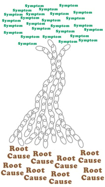
However, at the other end of the spectrum, the traceability requirement may include not only the list of equipment visited, but also the recipe used at each equipment, the precise timing of wafer movement and process modules visited within the equipment, values of any adjustable recipe parameters and/or equipment constants that affect process behavior, batch identification and status information for any consumables used during the process, usage counts for any fixtures involved, operator interactions (if any), and so on. The reason for this level of detail is to enable the failure analysis engineers to identify the potential root causes for any field failures, and then determine what other devices in the field may be susceptible to similar failure conditions for product recall purposes.

To be sure, much of this information could be assembled after-the-fact from the various data bases maintained by the equipment and process engineering and yield management systems present in most modern wafer fabs, but this process can be complex, time-consuming, and error-prone. A better approach would be to generate the most commonly needed traceability records on-the-fly directly from information available in the equipment... and this is where the newest EDA standards enter the picture. 

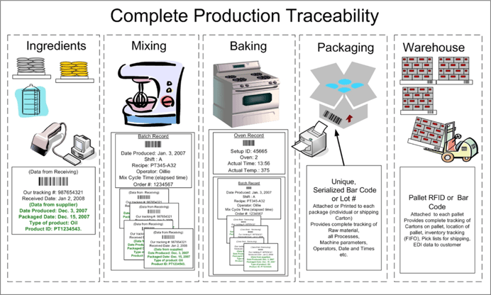
By analogy, let’s look at an intuitive example: a commercial cake baking enterprise. Even for a relatively simple (compared to semiconductor manufacturing) production process, full traceability requires information from the raw materials suppliers through the manufacturing process to packaging and finished goods warehousing. You can see in the picture below that material, recipe, and equipment setup information is included in the records produced.

Complete Production Traceability

In a unit of semiconductor manufacturing equipment with an E164-compliant interface, these types of information appear in various sections of the equipment metadata model. Specifically, material-related information is captured in the “Material Manager” logical component, shown in expanded view below* to highlight the state transition events and parameter data available for each substrate during its transportation and processing in the equipment.

Material_Manager_component

Recipe-related information is found in the physical modules responsible for substrate processing (“ProcessingChamber1” and “ProcessingChamber2” in the example below), within the “E157-0710:ModuleProcess” state machine, dictated by the SEMI E157 (Module Process Tracking) standard and required by E164. Note the rich list of context information available at every recipe step, including the RecipeParameters array, in the expanded model excerpt below. RecipeParameters_arrayTaken together, the timing and parameter data from these two sections of the equipment model supply most of the information required for full wafer fab traceability. Moreover, since SEMI E164 actually standardizes the event and parameter names in the model, the DCPs (data collection plans) that collect this information can be programmatically generated and activated for all the equipment that is E164-compliant. This represents a significant engineering cost reduction over the conventional methods used to identify, collect, and manage this information. The figure below is one visualization of such a DCP.DCP_Visualization

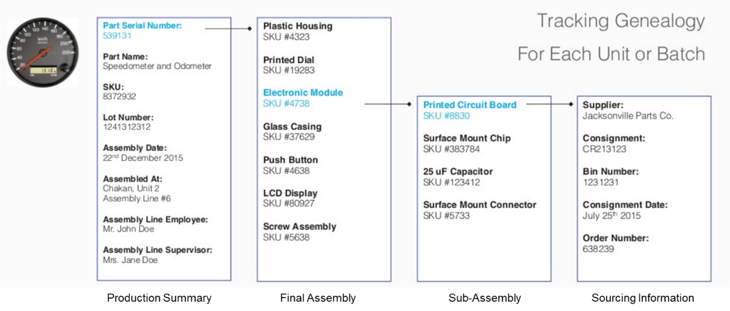
When extended beyond individual devices to circuit boards, modules, and completed parts (see the example below for an automobile speedometer), these requirements require even more bookkeeping… but that’s a topic for another day!automobile_speedometer

This article is the fourth in the series recently announced in the Models in Smart Manufacturing Series - Introduction, be sure to watch for subsequent postings that will expand on this theme. 

We look forward to your feedback and to sharing the Smart Manufacturing journey with you.


*The visualizations of equipment metadata model fragments and DCP contents are those produced by the Cimetrix ECCE Plus product (EDA Client Connection Emulator).
Topics: EDA/Interface A, Models in Smart Manufacturing series, Smart Manufacturing/Industry 4.0

Precision Data Framing during Process Execution – Tricks of the Trade: Episode 3 in the “Models in Smart Manufacturing” Series

Posted by Alan Weber: Vice President, New Product Innovations on Jun 27, 2017 11:30:00 AM

…or how to move away from “just in case” data collection...

It’s a common process engineering request of the manufacturing IT folks: “Please collect as much data as you can during this process, and we’ll figure out what’s important later.” And this approach has worked fairly well up to this point. However, with 10nm (and below) production on the horizon, coupled with the desire to sample key parameters at ever-increasing rates, the amount of on-line data storage required to support this approach could skyrocket… to say nothing of the difficulty in sifting through all that data to extract the real information you wanted in the first place.

Models3.1.jpgModels3.2.jpg

Fortunately, you don’t have to look very far into the SEMI EDA (Equipment Data Acquisition) standards (also known as “Interface A”) to find an excellent solution alternative. The portion of the standard equipment metadata model (specified by SEMI E164 – EDA Common Metadata) that deals with process execution (SEMI E157 – Process Execution Tracking) combined with the conditional triggering features of Trace Requests (SEMI E134 – Data Collection Management) enables a process engineer to precisely collect the right data at the right time at the right frequency without over-burdening the equipment or factory systems by collecting and storing less important data at the highest rates. 

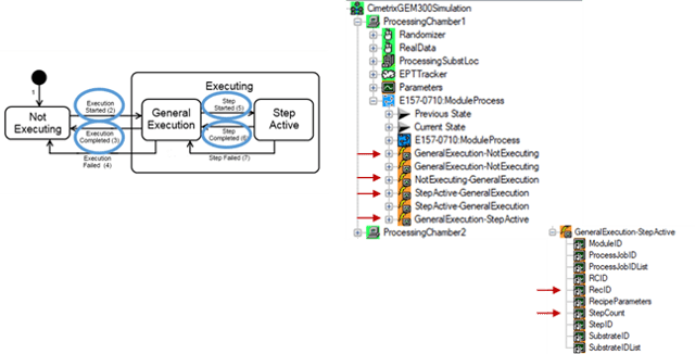
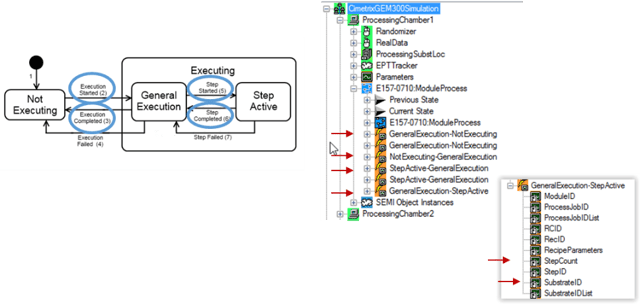
Let’s look at an example. The key state machine called for in the E157 standard (see figure below*) has 2 major states (NOT EXECUTING and EXECUTING) with intuitive transition events defined between them (Execution Started, Execution Completed, and Execution Failed). If you only care about tracking the overall execution time of the process recipes on a given tool, then a single DCP (Data Collection Plan) with a pair of Event Requests on the Started and Completed events is all you need. The difference in the timestamps of the corresponding Event Reports provides the necessary information. 

Models3.3.png

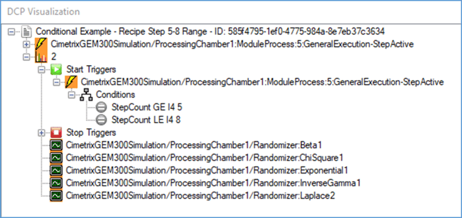
However, if you want to monitor a baseline set of equipment performance parameters at a low frequency (say, 1 Hz) throughout the recipe, and collect the key parameters for analyzing process behavior at a higher frequency (50 Hz) during the most critical process steps (5 through 8), you would use a DCP with multiple Trace Requests triggered by the Step Started and Step Completed transition events between the two sub-states (GENERAL EXECUTION and STEP ACTIVE) of the EXECUTING state. Furthermore, you would use the conditional triggering feature of the Freeze II version of the EDA standards (SEMI E134-0710 or later) to produce Trace Reports only during the critical process steps. The figure below is one visualization* of such a DCP.

Models3.4.png

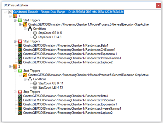
You may have noticed from this example that multiple triggering conditions are ANDed together to determine whether or not to collect the data and generate a Trace Report. But how do you handle the situation in which OR functionality is needed to produce the desired result, for example, in the case that multiple sets of recipe steps are considered critical (say, steps 5-8 and steps 11-13)?

This is where you can use one of the “tricks of the trade.” Simply define multiple Trace Requests with different sets of ANDed conditions to cover the range of ORed situations. For the case above, you would need two Trace Requests: one for each critical set of contiguous recipe steps (see visualization below).

Models3.5.png

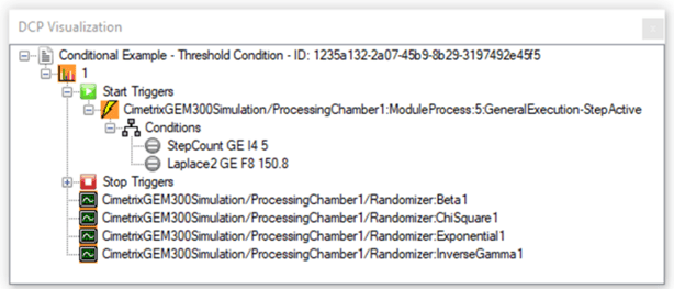
Note finally that you can also apply comparison operators to analog values to trigger Trace Requests, which may be especially useful to sample specific parameters when some value crosses an important threshold. 

Models3.6.png

Taken together, these techniques are sometimes called “data framing,” which is an important tool in the controlling the scope of factory data explosion that will soon be upon us. 

This article is the third in our Models in Smart Manufacturing series – be sure to watch for subsequent postings that will expand on this theme.

We look forward to your feedback and to sharing the Smart Manufacturing journey with you.

*The visualizations of equipment metadata model fragments and DCP contents are those produced by the Cimetrix ECCE Plus product (EDA Client Connection Emulator).
 

Topics: EDA/Interface A, Models in Smart Manufacturing series, Smart Manufacturing/Industry 4.0

Exposing Hidden Capacity through Material Tracking: Episode 2 in the “Models in Smart Manufacturing” Series

Posted by Alan Weber: Vice President, New Product Innovations on May 9, 2017 11:38:00 AM

“Do you know where your wafers are? Are you SURE?”

This adaptation of the famous public service announcement is as relevant for semiconductor process and industrial engineers as it was (and still is) for responsible parents. Given the ever-present productivity and profitability pressures in modern wafer fabs, it is essential to know the location and status of all product material at all times, because this information drives the scheduling and material delivery systems that provide competitive advantage for the world’s leading manufacturers. Until recently, material visibility at the lot/FOUP level was sufficient for this purpose, but this is no longer the case. 

Where_are_you.jpg

As production managers look for ways to squeeze more capacity out of their existing capital equipment, they realize that a deeper understanding of the wafer processing sequence within a particular tool type may provide opportunities to shorten the its overall lot processing time and increase the amount of material that can be processed simultaneously.  The first improvement results from identifying and eliminating unnecessary “wait” states* that individual wafers (or groups of wafers) may experience because of sub-optimal internal material handling, shared resource constraints, mis-calibrated subcomponents, poor recipe design, or a combination of these and other factors. The second improvement results from starting the next lot scheduled for a given tool as soon as all the wafers in the current lot have cleared the first stage of the process. This technique is sometimes called “cascading” or “continuous processing,” and applies to an increasing number of multi-chamber equipment types.

When applied to all the critical “bottleneck” tools in a factory, you can imagine what the resulting benefits would be for cycle time and capacity. Estimates of 3-5% improvement in these KPIs are not unrealistic.

Easy to say, right? But not so easy to implement? Perhaps not as daunting as you think…

The information required to track the precise location, movement, and status of individual wafers in semiconductor manufacturing equipment is most likely available for most equipment types in the form of “events” that chronicle the behavior of substrates, substrate locations, process chambers, aligners, wafer handling robots, and the other equipment components that affect wafer processing. What’s missing is a standard model that unifies this information across multiple equipment types, which would greatly simplify the data collection and analysis software required to implement a robust, generic material tracking system.

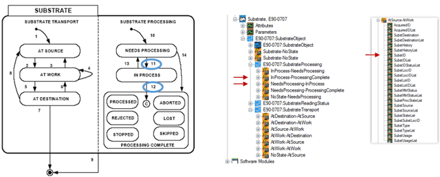
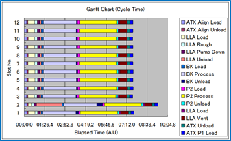
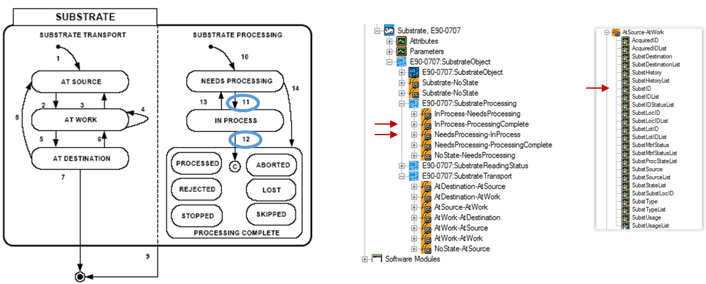
Here, too, the industry standards are actually ahead of today’s “state of the practice.” For example, the SEMI E90 “Substrate Management” and E157 “Specification for Module Process Tracking” standards define all the state machines, transition events, and associated context parameter data necessary to create a detailed Gantt chart of individual wafer movement and processing from start to finish, and allocate each contiguous time segment to its associated “active” or “wait” time element. The insights gained from this sort of visualization point directly to the opportunities cited above for improved tool control and factory scheduling.

Excerpts of these standards, a treeview representation of their respective models, and examples of the potential tracking displays are shown below.

Models_1.png

Models_2.pngModels_3.png

Models_4.png

Note that the SEMI E164 “Specification for EDA Common Metadata” calls for the inclusion of E90, E157, and a list of other GEM300 standards in the EDA equipment metadata model, so any E164-compliant equipment would directly and completely support such a material tracking application.

This article is only the second in the series recently announced in the Models in Smart Manufacturing Series Introduction posting – be sure to watch for subsequent postings that will expand on this theme.

We look forward to your feedback and to sharing the Smart Manufacturing journey with you.

*The list of potential “wait” states for semiconductor manufacturing has now been precisely defined and standardized as SEMI E168 “Specification for Product Time Measurement.” The standard also describes how they can be calculated using a specific set of standard material movement events commonly used in 300mm manufacturing equipment.

Topics: EDA/Interface A, Models in Smart Manufacturing series, Smart Manufacturing/Industry 4.0

Models in Smart Manufacturing Series – Introduction

Posted by Alan Weber: Vice President, New Product Innovations on Mar 24, 2017 11:30:00 AM

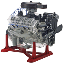
As a child I was an avid model builder—airplane models, trains, engines, cars, ships, even monsters (anyone remember “The Visible V8” and “The Creature”?)—anything I could get my hands on. At the time I didn’t reflect on the source of this fascination, but with the benefit of hindsight, it is clear that these models provided an interactive, tangible way to visualize, explore, understand, and enjoy the topics that were interesting to me. It was a way to enrich an otherwise intellectual activity.

Visible_V8.pngCreature.png

In fact, when Hurricane Carla ravaged the Texas coast and cut our electricity for 3 days, one of our luckier neighbors snaked an extension cord over the fence, which provided just enough power to run the refrigerator, a small black-and-white TV, and… you guessed it… my electric train. 

Model_train.png

More than four decades later, I still enjoy working with models, but in the high-tech manufacturing domain, they often operate in the reverse direction, providing a logical way to interact with and understand physical entities, like materials, fixtures, processes, devices, components, equipment, and entire systems. And as important as various model types have been throughout the relatively brief history of the semiconductor industry, they are increasingly an integral part of the “Smart Manufacturing” initiative that is sweeping a wide range of industries worldwide. 

The focus of my next few blog posts will be the specific models that are inherent in the communications interface definitions for manufacturing equipment, subsystems, and other devices that are expected to cooperate over the [Industrial] Internet of Things. Our first post in this domain almost a year ago introduced the notion that the metadata models called for in the latest generation of SEMI Equipment Data Acquisition (EDA) standards were already directly aligned with the Industry 4.0/Smart Manufacturing vision. This series goes into much more detail, showing how specific sections of the equipment models in the GEM and EDA standards directly support many of the factory monitoring, analysis and control applications that are essential for running a Smart Manufacturing enterprise (see Substrate Management example below).

substrate_management.png

Moreover, to the extent that the structure and content of these models can truly be standardized, their associated applications can be process- and supplier-independent, greatly reducing the development and support costs for the factory IT departments while providing useful capabilities for the production engineering and operations stakeholders.

To get a feel for the overall direction of this series, download the presentation "The Role of Models in Semiconductor Smart Manufacturing",  along with the transcript,  from the APC Conference held last October in Phoenix. Then watch for subsequent postings that address specific applications, from productivity (OEE) monitoring, material tracking, product traceability, process execution monitoring, and beyond.

We look forward to your feedback and to sharing the Smart Manufacturing journey with you.

Topics: Models in Smart Manufacturing series, Smart Manufacturing/Industry 4.0