 In the first blog of this series, Clare Liu of Cimetrix China made the compelling case for choosing a commercial software platform for implementing the equipment side of the EDA (Equipment Data Acquisition) standards interface rather than developing the entire solution in-house.
Whenever this “make vs. buy” decision is discussed, however, the following question inevitably arises: “If we choose a standard product for this, how can we differentiate the capabilities of our equipment and its data collection capability from our competitors?” It’s a great question which deserves a well-reasoned answer.
Platform Choice and System Architecture
Most advanced fabs use EDA to feed their on-line FDC (Fault Detection and Classification) applications, which are now considered “mission-critical.” This means if the FDC application is down for any reason, the equipment is considered down as well. It is therefore important to choose a computing platform for the EDA interface that is highly reliable and has enough processing “headroom” to support the high bandwidth requirements of these demanding, on-line production applications. Moreover, this platform should not be shared by other equipment communications, control, or support functions, since these may adversely impact the processing power available for the EDA interface.
Surprisingly, this approach is not universally adopted, and has been a source of problems for some suppliers, so it is an area of potential differentiation.
Adherence to Latest Standards
 The automation requirements for the most advanced fabs call for the latest versions (Freeze II) of all the standards in the EDA suite, including the EDA Common Metadata (E164) standard. Dealing with older versions of the standard in the factory systems creates unnecessary work and complexity for the fab’s automation staff, so it is best to implement the latest versions from the outset. The Cimetrix CIMPortal Plus product makes this a straightforward process using the model development and configuration tools in its SDK (Software Development Kit), so there is absolutely no cost penalty for providing the latest generation of standards in your interface.
It takes time and effort for equipment suppliers with older versions of the standards to upgrade their existing implementations, so this, too, is an opportunity for differentiation.
Equipment Metadata Model Content
This is probably the area with the largest potential for competitive differentiation, because it dictates what a factory customer will ultimately be able to do with the interface. If an equipment component, parameter, event, or exception condition is not represented in the equipment model as implemented in the E120 (Common Equipment Model) and E125 (Equipment Self-Description), and E164 (EDA Common Metadata) standards, the data related to that element cannot be collected. In effect, the metadata model IS the data collection “contract” between the equipment supplier and the fab customer.
 This is why the most advanced fabs have been far more explicit in their automation purchase specifications with respect to equipment model content, going so far as to specify the level of detailed information they want to collect about process performance, equipment behavior, internal control parameters, setpoints and real-time response of common mechanisms like material handling, vacuum system performance, power generation, consumables usage, and the like. This level of visibility into equipment operation is becoming increasingly important to achieve the required yield and productivity KPIs (Key Performance Indicators) for fab at all technology nodes.
The argument about “who owns this level of information about equipment behavior” notwithstanding, providing the detailed information the fabs want in a structure that makes it easy to find and access is a true source of differentiation.
Self-Monitoring Capability
If you really want to set your equipment apart from your competitors, consider going well beyond simply providing access to the level of information needed to monitor equipment and process behavior and include “built-in” Data Collection Plans (DCPs) that save your customers the effort of figuring out what data should be collected and analyzed to accomplish this. Your product and reliability engineering teams probably already know what the most prevalent failure mechanisms are and how to catch them before they cause a problem… why not provide this knowledge in a form that makes it easy to deploy?
A few visionary suppliers are starting to talk about “self-diagnosing” and “self-healing" equipment… but it will be a small and exclusive group for a while – join them.
Readiness for Factory Acceptance
 Before the fab’s automation team can fully integrate a new piece of equipment, it must follow a rigorous acceptance process that includes a comprehensive set of interface tests for standards compliance, performance, and reliability. This process is vital because solid data collection capability is fundamental for rapid process qualification and yield ramp that shorten a new factory’s “time to money.” If you know what acceptance tests and related software tools the fab will use (which is now explicit in the latest EDA purchase specifications), you can purchase the same software tools, perform and document the results of these same tests before shipping the equipment.
This will undoubtedly speed up the acceptance process, and your customers will thank you for the effort you took to put yourself in their shoes. Incidentally, this usually means the final invoice for the equipment will be paid sooner, which is always a good thing.
In Conclusion
In this posting, we have only scratched the surface regarding the sources of competitive differentiation. As you can see, choosing a commercial platform enables this far more readily than the in-house alternative, because it allows your development team to focus on the topics above rather than worrying about compliance to the standards. If you’d like to know more, please give us a call or click below to talk schedule a meeting.

 The Cimetrix Resource Center is a great tool for anyone who wants to learn more about industry standards including Equipment Connectivity and Control, data gathering, GEM (SECS/GEM), EDA/Interface A, and more. These standards are among the key enabling technologies for the Smart Manufacturing and Industry 4.0 global initiatives that are having a major impact on many industries. Manufacturers and their equipment suppliers must be able to connect equipment and other data sources, gather and analyze data in real time, and optimize production through a wide variety of applications. The free eBooks listed below provide in-depth coverage of the some of these concepts. They have been written by technical experts who have participated in and led the standards development processes for more than two decades.


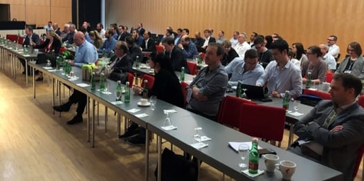
 Cimetrix participated in the recent European Advanced Process Control and Manufacturing (apc|m) Conference, along with over 150 control professionals across the European and global semiconductor manufacturing industry. This site of this year’s conference was Villach, Austria, a picturesque town nestled in the eastern Alps just north of the Italian border in the state of Carinthia. This region is home to a number of high-tech companies and institutions all along the semiconductor manufacturing value chain, and since it was the first time the conference was held in Villach, the local hosts rolled out the red carpet.
 Other highlights of the conference included:
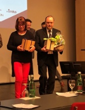 Another invited talk from BMW was delivered by Rainer Hohenhoff which covered “Product Data and Product Life Cycle Management in the face of new business models of the automotive industry.” In short, it discussed many of the ways a car company might make money even after people stop buying as many cars as they do today… and what collisions (pun intended) you could expect in the market as service companies like Google, Amazon, UBER, and others converge on the transportation consumer.
  The insights gained from these and the other 30+ presentations are too numerous to list here, but in aggregate, they provided an excellent reminder of how relevant semiconductor technology has become for our comfort, sustenance, safety, and overall quality of life.