Industry News, Trends and Technology, and Standards Updates

Designing Recipes in CCF

Posted by Derek Lindsey: Product Manager on Jan 24, 2017 11:00:00 AM

Anyone above a certain age will be able to tell you what you get when you combine two all-beef patties, special sauce, lettuce, cheese, pickles, onions – on a sesame seed bun. There are many who would argue that what sets a Big Mac apart from other burgers – and has made it one of the best-selling products of all time – is the special sauce.

In a March 2016 blog post, Cimetrix listed eleven points to be taken into consideration when starting an equipment control application using CIMControlFramework (CCF). One of the things to consider is how you want to provide process and path information through the tool using recipes. This blog post delves a little deeper into the recipe aspect of equipment control applications.

In CCF, recipes are either process recipes or sequence recipes.

Cookbook1.png

A process recipe contains the instructions to be carried out by a particular process module. These instructions can range from temperature settings to types of gas to flow. The most important aspect of any tool control application is allowing the tool manufacturer to do what they do best – perform their process better than anyone else in the world. The process recipe allows tool manufacturers to add their special sauce to the wafer. CCF provides a sample process recipe implementation as well as very simple process recipe editor. Since recipes are generally custom for each tool manufacturer, CCF application developers usually want to customize the recipe contents for a process recipe.

If the processing of material is the special sauce, the rest of the application, moving the wafer through the tool, is a necessary evil. To assist in moving material through the tool, CCF also provides a sequence recipe. A sequence recipe determines which process recipes are to be run, at which modules to run them, and the order in which this is to occur. CCF provides a sample sequence recipe editor that can be used in creating sequence recipes or customized for each tool manufacturer’s needs.

Both process and sequence recipes can be created on the tool or downloaded from a factory host. CCF provides a handler that receives recipes from the host and stores them in the Recipe Server. Regardless of where the recipes are created, CCF’s Recipe Server stores the recipes locally and passes them in to the scheduler when a job is to be run. The Recipe Server allows recipes to be stored as Engineering recipes while they are being finalized. They can then be promoted to Production recipes for use in a production environment. 

By making use of recipes in CCF, you can ensure that your special sauce is applied to material processing to help make your tool one of the best-selling in history.

To learn more about CCF, visit the CIMControlFramework page on our website! 

Topics: Equipment Control-Software Products, Cimetrix Products

Fall 2016 SEMI Standards Meeting

Posted by Brian Rubow: Director of Solutions Engineering on Jan 18, 2017 11:30:00 AM

SEMI_logo_share.jpg SEMI North America Information & Control Task Force and Committee fall meetings were last held at SEMI headquarters November 7 through 9, 2016. During these meetings, SEMI announced that they are relocating their headquarters to Milpitas, CA. That move is currently underway. In the GEM 300 task force, all of the ballots failed to pass. This include ballot 5872A, 5549, 6026, 6066, and 6068. In the DDA task force, ballot 6064 also failed.

Ballot 5872A is work driven by Cimetrix to complete to work initially proposed for the E172 standard SEDD files, a feature to enable an electronic format for GEM documentation. Ballot 5872A failed due to some minor issues. SEDD files already provide partial GEM interface documentation in an XML file by listing the data variables, status variables, equipment constants, collection events and alarms. The ballot proposes to enhance SEDD files by adding a list of supported SECS-II messages, remote commands, SEMI standards (with compliance tables), and default event reports. The ballot will be reworked and resubmitted as ballot 5872B.

 Ballot 5549A is a title change and organizational change to the GEM E30 standard. Several years ago, SEMI required all standards to have an official designation, such as Guide or Specification. E30 currently has a title that fails to establish an official standard designation. Additionally, the standard currently fails to have the mandatory sections “Purpose”, “Scope”, “Limitations” like other standards. The ballot was delayed several years due to the SML copyright claim by Peer Group and the ensuing legal confrontation with SEMI. The ballot was finally submitted in 2016 and failed because it renamed the Application Notes as an Appendix instead of “Related Information”. Additionally, there was some confusion because the ballot was based on the 0611 version of E30 rather than the 0416 version which had just been published. This ballot will be reworked and resubmitted as ballot 5549B.

 Ballots 6026, 6066, 6068 and 6024 are reapproval ballots for standards E109, E130/E130.1, E116/E116.1 and E121. SEMI automatically submits all standards for re-approval every five years if a standard has not been revised. These standards all failed due to outdated references. They will all be resubmitted in 2017 with minor changes to correct the outdated references.

 The new GUI task force was approved to create a new major revision of the E95 standard. In particular, the new revision will accommodate new software and hardware technology when laying out equipment user interfaces.

 Cimetrix proposed a new activity to define new SECS-II messages for transferring recipes. The activity will result in a new ballot 6614. Currently, the GEM standard defines two ways to transfer unformatted recipes. Using simple Stream 7 messages S7F3 and S7F6, the entire recipe is part of a single message. This makes is really easy to implement in the host and equipment GEM software, but recipes are limited to about 16.7 MB (the maximum size of a single data item in any SECS-II message). The second way is using the large recipe scenarios which involve using a sequence of messages S7F43/F44, S13F1/S13F2, S13F3/F4, S13F5/F6 (repeated iteratively until there is an error), S6F11/F12 and finally S13F7/F8. Even for an expert, this is very complicated. Ballot 6614 will propose simple new messages for transferring a large recipe using a single message where the recipe can be broken up into multiple parts where each part is up to 16.7 MB in size. If approved, another ballot will attempt to add this to GEM standard. This will open the door for the GEM standard to be used more effectively and in more application where the 16.7 MB limitation posed an issue.

 Japan Information & Control committee (I&CC) announced the official withdrawal of OBEM standards E98 and E98.1. Japan also announced a GEM300A initiative which includes standards E170 and E171 and E174. E170 is the Production Recipe Standard which allows equipment to designate production and non-production recipes; where production recipes are given change protection. E171 defines predictive carrier logistics. Ballot 5601 defines Wafer Job Management. It is not clear whether or not there any IC makers will demand any of these newer standards. Of the three, E170 seems to be most useful and interesting. Predictive carrier logistics seems to be useful only for equipment that have carrier internal buffers. It attempts to help the equipment report when carriers will be ready for removal. It is not clear how E171 will compete with the upcoming E87 ballot 4946 to be submitted by the Korean Information & Control Committee in 2017. Ballot 4946 modified the E87 standard to predict when carriers will be ready to unload. Wafer Job Management is a controversial standard. Japan I&CC announced the passing of ballot 5601 (now E174) despite the strong opposition by multiple knowledgeable voters in other regions, and despite very underwhelming support from regional leaders in North America, Korea, Europe and Taiwan.

 Korean Information & Control committee announced plans to submit ballot 5832, a proposal for a new Generic Counter standard which is built upon the GEM standard. The standard would allow an equipment to define various types of generic “counters” that can be reset by the host. The counters could be used a wide variety of applications; particularly predictive maintenance. The standard as defined in the current ballot defines digital counters, analog counters and collection event counters. Voting period for this ballot just ended recently.

 Next North American I&CC meetings will be held first week in April, 2017.

Topics: Industry Highlights, Semiconductor Industry, Events

Create Operator Interface Screens Using CCF

Posted by Harley Pebley, Software Craftsman on Jan 5, 2017 1:31:00 PM

Our bodies are amazing machines. Ask a man off the street what they see when they look at someone, they will probably talk about skin, hair and eye color, height and weight and other external defining characteristics. Ask a doctor and they may see issues relating to what’s going on in the person’s organs and overall internal function. Ask a molecular biologist and they’ll talk about the chemical pathways that allow things to work at the cellular level. Much like our bodies, computer controlled systems are made up of many layers. Starting with electrons moving through conductive and semi-conductive materials, abstraction layer is added upon abstraction layer to create components, circuits, assemblies until finally a computer is created. In the same way layers of software control this computer from the BIOS up through layers in the operating systems and culminating in the application the user sees. Similar to the way doctors and biologists work at different levels of abstraction within their domains, we as engineers know about, work with and think about our system at various abstraction levels. However, the end user is like that man on the street, all they see are the external characteristics. Because of this, the operator interface is among the most important parts of the system.

SEMI established the E95 standard as general guidelines for screen layout of tool control software. CIMControlFramework (CCF) provides a standards conforming shell into which various screens may be added to create a complete operator interface. This allows the tool manufacturer to focus on the unique needs of their tool and have no worry about meeting the standard.

There are several general steps to create an operator interface using CCF:

  1. Decide on the technology. In the Windows desktop software world, there are two primary ways of developing a user interface: WinForms and Windows Presentation Foundation (WPF). CCF has historically supported the WinForms environment providing many fully functional WinForms screens. It has also supported WPF, but only provided a single example WPF screen. Cimetrix is in the process of updating WPF support and adding multiple fully functional WPF screens out of the box. Either environment may be used based on what the tool manufacturer’s developers deem appropriate.

  2. Establish the requirements. The purpose of the operator interface is for the tool to provide the operator with information about what it’s currently doing and for the operator to tell the tool what to do. Determining the correct way to do this can be one of the hardest parts of designing a user interface. This step is where the best level of abstraction is established. The user should have sufficient information to understand what’s happening without being overwhelmed by too much data. The user should also have enough control to do what needs to be done without having to worry about too many details. The analysis for this step is often done by multi-disciplinary teams using analog methods like whiteboards and pen and paper. Creating avatars for different types of users and then writing stories about what those users will want to do is a good way to help flesh out what’s needed by the operator interface.

  3. Evaluate pre-built screens against the requirements. Once the target is established, the screens provided by CCF can be examined for fitness. How well do they fit the target? Some screens may be close enough to the requirements to be used as is. Other screens may be close but require some tweaks to meet the specific needs. Finally, some screens may need to be built from components provided by CCF to satisfy the unique specifications of a particular tool.

  4. Assemble the screens into an application. Once a list of needed screens is created, the final step is to put everything together. This is generally the most time consuming part of building an operator interface. This phase is when any custom screens are built or modifications made to existing screens. Finally, all the screens, both custom and pre-built, are added to the framework provided by CCF. CCF has a number of labs to help understand how the various user interface components work together to provide a cohesive whole.

CCF provides the structure, pre-built screens and tools to assist in creating custom ones to give your tool a beautiful skin.

To learn more about CCF, visit the CIMControlFramework page on our website!

Topics: Equipment Control-Software Products, Cimetrix Products

Create a Scheduler Using CCF

Posted by Derek Lindsey: Product Manager on Dec 14, 2016 11:30:00 AM

Shel_Silverstein_MelindaMae.jpg

How do you eat a whale? One bite at a time. 

In a March 2016 blog post entitled CIMControlFramework Work Breakdown, Cimetrix listed eleven points to be taken into consideration when starting an equipment control application using CIMControlFramework (CCF). One of the things to consider is how you want to control the material moving through the tool – or scheduling of material. This blog post delves a little deeper into the scheduling aspect of equipment control applications.

Doctoral dissertations and entire books have been written to discuss scheduler theory. Because of sheer volume of information available regarding scheduling and scheduling theory, the topic can come across as a little (or a lot) intimidating. CCF aims to take the scare factor out of scheduling and allow equipment control application developers to fully control the movement of material through their tool.

CCF provides a framework for a reactive, rule-based scheduler. You, as the application developer and in conjunction with your customer needs, get to decide what decisions are important when creating your scheduler. One of the first things you need to do when developing a scheduler is to ask questions to help you determine the rules for scheduling. Some questions you may ask:

  • What is the most important thing I am attempting to accomplish with my scheduler?

    • Is throughput the most important?

    • Is path predictability most important?

  • How can I ensure that when I pick material up that there is a destination available to put it?

  • If two components need a robot to take action (pick up or place material), which action takes precedence?

  • Do the process chambers need to be prepared before receiving material to process?

  • What is the wafer flow scenario (is there a specific order that material must follow)?

    • Does the material need to be aligned before processing?

    • Does the material need to be acclimatized before processing?

    • Does the material need to be cooled before returning to the carrier?

  • Are there any maintenance tasks that have to be performed periodically in the tool that have to be accounted for in scheduling?

This is by no means an exhaustive list of questions, but these are the types of questions that need to be answered when creating your scheduler. 

The scheduling framework provided by CCF allows you to translate these rules into C# conditional statements. No proprietary scripting languages need to be learned. No specific configuration training is required. C# developers can use industry standard IDEs to put these rules into scheduling practice.

Once the scheduling rules are determined, it can still be intimidating to know how to start creating your scheduler. Cimetrix provides a few basic, as well as more advanced,of  scheduling labs that fully explain how to translate your rules into a functional scheduler. These labs can be completed in as little as a few hours. The labs explain the scheduling theory used by Cimetrix and allow users to create functional schedulers in a short amount of time. Many CCF users can create a working scheduler in one week.

Cimetrix also provides complete working examples of atmospheric and vacuum schedulers as part of CCF. Another lab provided by Cimetrix clearly describes how to start with one of these working schedulers and modify it to suit your scheduling needs.

The CCF scheduling framework allows the software to be hardware agnostic. In other words, it is not tightly coupled to device drivers. This allows tool manufacturers to change out hardware without having to make scheduler changes to support the new hardware.

Although scheduling may seem like an intimidating whale to eat, CCF helps break the tasks down into bite-sized chunks.

To learn more about CCF, visit the CIMControlFramework page on our website!

Topics: Equipment Control-Software Products, Cimetrix Products

Create Device Drivers Using CCF

Posted by Tim Hutchison: Senior Software Engineer on Dec 6, 2016 11:30:00 AM

In 1976, Blue Oyster Cult released their hit song, “Don’t Fear the Reaper”.  In 2000, Saturday Night Live produced a fictitious, but humorous skit around the production of the “Don’t Fear the Reaper” called, “More Cowbell”.  The “More Cowbell” skit put a very light hearted spin on the production of the hit song.   After seeing that skit, I can never hear that song the same way. The cowbell, for as small a piece it plays, is a huge part of the song.

Keep_Calm_Cowbell.jpg

The same can be said for the hardware that is used in Semiconductor manufacturing tools.  Tool control boils down to controlling the hardware. Without controlling the hardware, the UI and factory automation will not amount to much if the robot doesn’t move. Everything from the robot, down to a simple presence sensor on a load port is needed. What may seem to be the simplest device can be the most prominent.  Each device plays an important part in the process. 

A Cimetrix blog post on March 15, 2016 entitled CIMControlFramework Work Breakdown, identifies driver integration as one of the first steps that needs to be done in the work breakdown for a CIMControlFramework (CCF) application. It may seem intimidating to create a driver to control hardware. There is the need to connect to the device. There is some number of commands and possible responses to deal with.  It can be overwhelming, but can be conquered by understanding what needs to be done to control a device through a driver.

Let’s look at how to go about developing a driver.

  1. Understand the interface to the device using any and all documentation available.  The documentation will provide information on how to send commands and interpret the responses.
    1. Does the device control only one device or many?
    2. What is the communication protocol to the device?
      1. TCP/IP
      2. Serial ports
    3. What are the commands?  How are the commands composed?
    4. What are the responses?
    5. Will the device need to be polled?
    6. Will the device send unsolicited messages? 
  2. Understand what needs to be controlled on the device for the tool. 
    1. Will you only need to use a subset of the interface or the entirety of the interface?  If just a subset, then there is only a need to write those initially.
  3. Writing code to “talk” to the device
    1. Do you have a simulator for the device?
      This one is important, especially if the hardware has limited availability.  If needed, a simple simulator can be developed to at least validate communications, then expanded over time to simulate faults or other conditions.

      As the tool begins to come together, each simulator will become invaluable when developing the other parts of the tool and coordinating the devices together. 
    2. Unit tests can be useful to verify that the driver behaves as expected before using on actual hardware.  Unit tests can also provide regression testing should changes be made to a driver.
      Some areas to consider unit testing;
      1. Handling of failure to connect
      2. Handling of failure to send to the device or receive from the device
      3. Handling of return values
    3. Start out simple, just get a connection to the device to begin with.  Next send a simple command and inspect the response.  Create a success and build upon the successes!

In the end, a driver will be sending commands and getting and interpreting a response. For every device you create a driver for you’ll also become the expert on that device.

Even though it can be intimidating to start, developing drivers is one of the fun parts of tool development. There is nothing more exciting than seeing the hardware begin to dance in the fashion that has been choreographed in your software

CCF provides utilities and examples to help create drivers for your hardware and easily integrate them into the application, to assist you to orchestrate and provide more cowbell in your tool control. 

To learn more about CCF, visit the CIMControlFramework page on our website!

Topics: Equipment Control-Software Products, Cimetrix Products

Leveraging GEM

Posted by David Francis: Director of Product Management on Nov 28, 2016 11:30:00 AM

One of my favorite gifts when I was a kid was an erector set. I could build all kinds of machines and robots. The set I had even included a simple motor, so I could make things move. I spent a lot of hours building machines and robots and dreaming of doing that on a bigger scale.

When I graduated from college I worked for a small company that did warehouse automation and automated transport control systems. It took me back to when I was a boy building robots with my erector set. Except these robots could actually move things and had a full set of commands to control them, not just on or off. The company I worked for had a small group that did firmware programming for the robotic controllers. I worked in the software group that wrote the software systems for controlling the whole automated warehouse. I soon learned that each type of automated equipment had its unique set of commands and that just because two pieces of equipment might perform the same function, didn’t mean they used the same commands.

Along the way I had the opportunity to work with Motorola to develop cell controllers for one of their new, state-of-the-art fabrication facilities in Austin, Texas. This opened up a new world of automation for me. The SEMI Equipment Communication Standards (SECS) were fairly new and still trying to gain wide acceptance. There were a lot of similarities to the automated material handling equipment I had been working with. Each piece of equipment had a defined set of SECS messages it supported, but each tool had to be carefully characterized in order to know how to create the cell control application that would interface with it. It was exciting to bring new tools on line and see the benefits in reduced scrap and improved throughput. But it took a lot of time to develop the cell controllers and there wasn’t much code that could be reused from one to the next.

During this time, I had the opportunity to attend some SEMI standards meetings and participate in discussions about the development of a Generic Equipment Model (GEM) to achieve more consistency across different companies’ SECS interface implementations. It made so much sense! I had built a good business doing equipment characterizations for semiconductor manufacturing companies, but it seemed like there should be a better way of interfacing with the equipment – a more standard way. As the adoption of GEM grew in the semiconductor manufacturing industry, the cost of developing equipment cell control applications decreased. Much of the code could be used across different pieces of equipment, because there was a standard for interfacing with all equipment.

While GEM was developed by and for the semiconductor industry, it could also benefit many other industries. GEM provides a standard way to control a factory and gather equipment and process data that can be used to measure and monitor Overall Equipment Effectiveness (OEE), implement Statistical Process Control (SPC), manage material queues and WIP levels, and a wide range of additional factory applications. Several parallel markets (PV, LED) have adopted the GEM standard to take advantage of commonality required by the standard. Other markets would also benefit by adopting the GEM standard to help increase software reuse and productivity


Topics: SECS/GEM

EDA Metadata Conformance Testing

Posted by Derek Lindsey: Product Manager on Nov 15, 2016 11:00:00 AM

In a recent blog posting we introduced the topic of EDA (Equipment Data Acquisition) standards testing and sub-divided the domain into three parts:

  • Compliance testing – does the equipment adhere to the specifications described in the SEMI Standards?

  • Performance and stability testing – does the equipment meet the end users’ performance and availability specifications?

  • Equipment metadata model conformance testing – does the equipment model delivered with the interface represent the tool structure and content anticipated by the end customer?

Today’s post deals with the equipment metadata model conformance testing in greater detail.

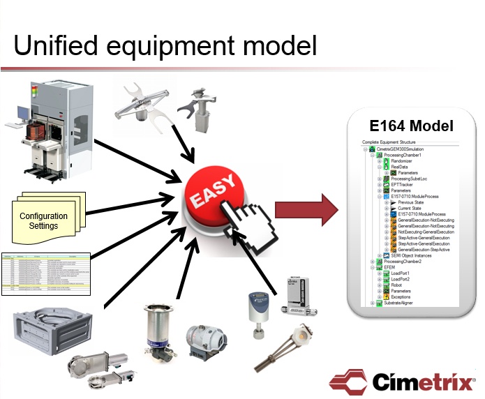
The impetus for the metadata conformance requirement is SEMI Standard E164 – Specification for EDA Common Metadata. Although this standard is not part of the original core suite of EDA standards, it is now being required by GLOBALFOUNDRIES and a number of other major semiconductor manufacturers on EDA-enabled equipment.

The purpose of the standard “is to promote commonality among implementations by defining common representations and conventions of equipment metadata based on SEMI E125.” (Section 1.1 of E164)

In other words, conformance to E164 requires a consistent implementation of E125. All state machines required by the GEM300 standards must be implemented and use the same names for required events, parameters, state names and transitions. It requires that all process modules implement the E157 Module Processing state machine using specified names. As a result, E164 ensures a high level of implementation commonality across all equipment types. This commonality enables better automation of data collection processes across the fab, driving major increases in engineering efficiency. In summary, E164 is to EDA what GEM was to SECS-II.

Currently, the only E164 conformance tester is Metadata Conformance Analyzer (MCA) that was commissioned by Sematech and implemented by NIST (National Institute of Standards and Technology). In our discussions with potential users of an EDA test tool, most clients agree that the sooner a replacement can be created for MCA, the happier they will be.

In a previous post, we mentioned that Cimetrix has automated the EDA compliance evaluation procedures. We are also in the process of designing the performance testing components of this tester. The plan is to also create an E164 conformance tester that will replace MCA.

If you want to know more about EDA testing and/or discuss your specific needs or provide input on what you would like to see included for E164 conformance testing, contact Cimetrix for a demonstration of this exciting new capability!


Topics: Industry Highlights, EDA/Interface A, EDA Testing Series

Semicon Europa 2016 is in the books!

Posted by Kimberly Daich; Director of Marketing on Nov 10, 2016 11:30:00 AM

SEMICON Europa was held in Grenoble France this year from October 25-27, 2016.  Grenoble is a hot point for semiconductor technology in France with fabs and technology centers located close by.  Typically, this trade fair moves between Dresden and Grenoble each year with attendance of about 6000. 

IMG_4214.jpg

The Cimetrix team consisted of Dave Faulkner, EVP Sales & Marketing; Bruce Febvret, Business Development,  Europe; and Kimberly Daich, our new Marketing Manager.  Cimetrix brought our new double wide booth with new branding and was located next to our integration partner Agileo Automation.  

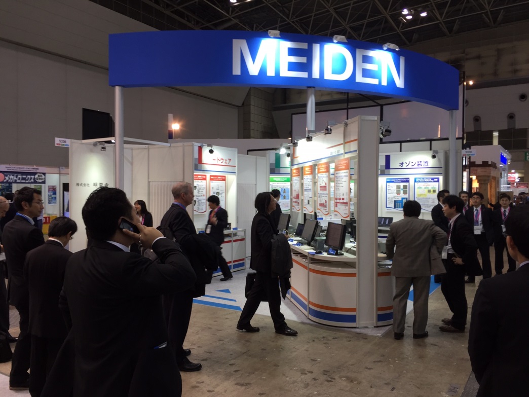
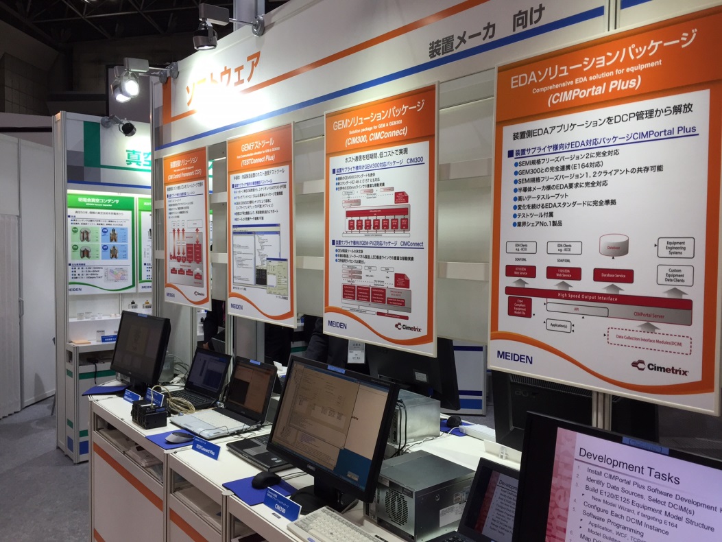
IMG_3302.jpgWe highlighted our CIMPortal Plus software demonstrating the benefits of the SEMI E164 standard.  Attendance seemed light this year which allowed the Cimetrix team ample time to meet with various equipment supplier customers who had exhibits at the show. Of particular interest to our customers was our advice on when and how to add Interface A to their control systems, and what impact Industry 4.0 and smart manufacturing will bring.  The evening networking event was very well done; congrats to the SEMI team.IMG_3326.jpg

SEMI made an importance announcement that starting next year, SEMICON Europa will no longer move back and forth between Grenoble and Dresden; and will move to Munich in mid-November.  This allows one large show featuring SEMICON and Productronica.  SEMICON Europa will focus on semiconductor related activities and Productronica will focus on electronics assembly technologies.  This decision works very well for Cimetrix as we share customers in both industries. See you next year in Munich!


Topics: Semiconductor Industry, Events

EDA Performance Testing

Posted by Derek Lindsey: Product Manager on Nov 1, 2016 1:00:00 PM

Update: Cimetrix EDATester Datasheet available now!

In a recent blog posting we introduced the topic of EDA (Equipment Data Acquisition) standards testing and sub-divided the domain into three parts:

  • Compliance testing – does the equipment adhere to the specifications described in the SEMI Standards?

  • Performance and stability testing – does the equipment meet the end users’ performance and availability specifications?

  • Equipment metadata model conformance testing – does the equipment model delivered with the interface represent the tool structure and content anticipated by the end customer?

Today's post deals with the performance and stability testing in greater detail.

In our discussions with EDA users (both OEM implementers and fab end users) about EDA testing, they all acknowledge the need for compliance testing. However, the vast majority have said, “If you can help me automate my performance testing, I would be able to save a huge amount of time.” Most thought they could reduce testing time from several weeks to just a couple of days.

Everyone has different ideas about what should be included in performance testing of their EDA software. Everyone can agree that generally they need to test if the equipment meets the end users’ performance and availability specifications in terms of data sampling intervals, overall data volume transmitted, size and number of DCPs (data collection plans) supported, demands on the computing/network resources, and up-time. They also need to know if the software will support the range of application clients expect in a production environment.

Data Volume

EDA users want to know the sheer volume of data that can be collected.

ISMI has reported in public forums that IC makers expect EDA to achieve data rates of 50+ variables per chamber at rates up to 10 Hz. In EDA specifications, IC makers have requested the ability to gather 1,000 to 2,000 parameters using data collection rates from 5 to 20 Hz, which translates to 40,000 values per second.

These rates are easily achievable with today’s computing platform technology, but users also want to know the upper limit. In other words, at what point does the ability to collect data break down?

Data Quality

EDA users want to know that the data comes in at the specified rates and that the values and timestamps that are received at those rates are accurate.

Resource Usage

EDA users want to know how different data collection rates and volumes will affect the system resources. Will memory usage be too high? How will different collection rates affect CPU usage? Is the network bandwidth sufficient for gathering the required data at the required speeds and still maintain high data quality?

In a previous post, we mentioned that Cimetrix has automated the EDA compliance evaluation procedures. The newly released Cimetrix EDATesterTM is the integrated solution that supports the broadest range of use cases in SEMI Equipment Data Acquisition (EDA/Interface A) standards compliance testing in the industry. The Cimetrix EDATester automates the execution of the ISMI EDA Evaluation Method and features performance testing that characterizes the capabilities and limitations of a tool’s EDA interface. Download the data sheet and see how the Cimetrix EDATester supports your objectives. 

If you want to know more about EDA testing and/or discuss your specific needs, contact Cimetrix for a demonstration of this exciting new capability!


Topics: Industry Highlights, EDA/Interface A, EDA Testing Series

EDA Compliance Testing – Scope and Approach

Posted by Alan Weber: Vice President, New Product Innovations on Oct 19, 2016 11:30:00 AM

In a recent blog posting we introduced the topic of EDA (Equipment Data Acquisition) standards testing and sub-divided the domain into three parts:

  • Compliance testing – does the equipment adhere to the specifications described in the SEMI Standards?

  • Performance and stability testing – does the equipment meet the end users’ performance and availability specifications?

  • Equipment metadata model conformance testing – does the equipment model delivered with the interface represent the tool structure and content anticipated by the end customer?

Today’s post deals with the first of these parts in greater detail.

To begin, we should point out that standards compliance testing is not a new idea – it has been an integral part of the acceptance testing process for automated manufacturing equipment for decades. As each new generation of SEMI’s communications standards (SECS-II, GEM, GEM300, and now EDA / Interface A) reached critical mass, the compliance testing process naturally evolved from an ad hoc, manually driven set of procedures to a more thorough, formal process supported by automated testing software. Moreover, the use of this kind of software and the reliance of leading chip makers on its results has greatly contributed to the efficiency of the overall new fab startup and initial yield ramp process, so its importance to the industry cannot be overstated.

So where does the industry turn for information about how to test for EDA standards compliance?Although the Sematech manufacturing consortium’s R&D program no longer includes SEMI Standards definition, validation, and promotion support, the work that its ISMI subsidiary (International Sematech Manufacturing Initiative) did in the formative years of the EDA standards is still directly applicable. In particular, the “ISMI Equipment Data Acquisition (EDA) Evaluation Method for the July 2010 Standards Freeze Level: Version 1.0” is the globally accepted approach for checking compliance of an equipment’s EDA interface.

 ISMI2.png

This document takes an automation test engineer through the entire set of steps for connecting a tool to a known-compliant test client (in this case, the Cimetrix Equipment Client Connection Emulator, or ECCE Plus product), adding entries to the interface’s Access Control List (ACL), uploading and inspecting the equipment metadata model, managing Data Collection Plans (DCPs), and invoking all the other services defined by the SEMI EDA Standards suite (E120, E125, E132, E134, E164, etc.). Its appendices not only define the required procedures in detail, they also describe the expected results and suggest a format for reporting these to interested stakeholders.

Of course, those familiar with the use of this method and the associated software tools know that it can take 2-3 days to execute this process manually, which is an inefficient way to check compliance for the incoming tool set of an entire fab. Fortunately, there IS a better approach. Cimetrix has automated these evaluation procedures in a way that ensures the target equipment meets the automation software purchasing requirements to the satisfaction of both the equipment supplier and the semiconductor manufacturer, while leaving the door open for factory-specific requirements that represent unique competitive advantage.

Note that ISMI and its member companies also recognized that much of the potential value of the EDA standards would be derived from (and limited by!) the content of the equipment metadata model, so they funded the development of another software tool to check these aspects of a supplier’s implementation. But that is a topic for an upcoming blog – watch for it.

So… if you want to know more about EDA testing and/or discuss your specific needs, contact Cimetrix for a demonstration of this exciting new capability!

Alan Weber
VP, New Product Innovations
Cimetrix Incorporated

Topics: Industry Highlights, EDA/Interface A, EDA Testing Series