Hi folks! We in the CCF (CIMControlFramework) Services Team love training/consulting on CCF implementations and building custom software for our customers. We’re especially thrilled when we can help our customers ship new equipment and subsequently hear that the equipment successfully ran thousands millions of cycles without issues.
Recently, we enjoyed helping one of our customers build a tool that processes non-wafer substrates. The tool control system included some typical components such as Rorze Hardware Drivers, Light Tower drivers, and a Load Port E84 IO Control, but had some more unique capabilities as well. In this posting we will explore some of the challenges posed and advantages realized from these special capabilities. Before we dive in, please allow me to give a shout out to John Last, our Senior Software Engineer who designed and built most of these capabilities.

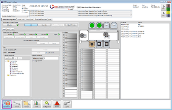
Process Module Operation Screen
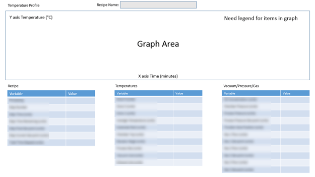
Rather than simply logging data points, our customer wanted a visual representation of temperature over time (minutes). We displayed the categorized variables and their values in tables as well, but the graph updating in real time made it much easier for the operator to visualize the patterns and identify risk events and their sources. The graphing feature needed to be active whether or not the process module operation screen was being displayed. Moreover, It had to handle 3 different step types (Ramp, Dwell and Cool).
Calculating the Y-Axis range for this display presented an additional interesting challenge. The minimum and maximum values were determined by searching all recipe steps and selecting the lowest and highest value setpoints, then subtracting a fixed number from the lowest to get the Y-Axis minimum value and adding a fixed number to the highest value to get the Y-Axis maximum value. The figure below shows how the expected process data should look compared to the observed process data. This allows the operator to see what the equipment is expected to do compared with its actual behavior.

Partial FOUP grouping to create a single batch
Our customer required the capability to group multiple partial FOUPs into a single batch. This is especially useful in scenarios where partially filled FOUPs would be used—say, in R&D environments. In other words, we needed to support scenarios where the number of FOUPs needed for processing a batch exceeded the number of load ports. This required us to create Control Jobs with a MtrlOutSpec containing a valid SourceMap with an empty DestinationMap. We relied on SEMI E94’s concept of “Late Announcement of Output FOUP” to specify the input FOUP but not the output FOUP. This allows the scheduler to say, “We know the substrate will go to a different slot, but we won’t tell you which slot until later.”
E90 substrate reading in the Panel solution
As with most tools, each of the substrates has an ID, and this ID must be read and reported to the host. In this case, our host had to verify that the expected ID matched the actual ID. On a successful match, the equipment would then continue the job. If it failed, however, the host would be notified and decide whether to proceed or change something. Capabilities like these maximize throughput and mitigate risks to equipment safety side and production scrap.
Different Panel Types
This machine was required to deal with panels having multiple thicknesses and possible warpage. Therefore we needed to provide a method for an operator, the recipe, and the host to specify the panel type to be processed. None of the variations of panel types were known ahead of time, so we needed methods that handled additional panel types without having to make code changes after the equipment was deployed in production.
The tool also required different substrate mapping parameters for each panel type. Because panel type was specified in the process program referenced in the Process Job, the panel type was not known when the FOUP arrived at the load port. To handle this situation, we customized a standard factory automation SECS II message to communicate the panel type from the host to the tool on arrival of the FOUP.
Conclusion
This equipment was built on an extremely aggressive timeline by a very small team. I was particularly impressed by the team’s ability to grasp the end customer’s requests and creatively explore alternative ways to solve the never-before-seen challenges. In summary: no drama; a few delays; even fewer verbal altercations; just a little frustration; only a little scope creep; and most important, a satisfied factory customer. We all cheered when our customer shipped the tool in 2020.
To find out more about CIMControlFramework and our CCF Services team, or to contact us for a demo, click the button below.


.png)


